
Technical Trivia by Dr. FB
A slightly unusual specification of an analog multi-meter

Dr. FB
Hi. My name is Fine Business. Many people call me Dr. FB, for short. I have a lot of hobbies, but I really like to operate amateur radio. I have my main profession, but sometimes I want to share what knowledge I have here.
1. A slightly unusual specification of an analog multi-meter
Many readers have a multi-meter. Recently, most multi-meters seem to be digital types. I still use an analog type multi-meter, shown in Figure 1, because a technician like me doesn't need to read to the last digit of the voltage to repair electronic equipment, or do electronic work.

Fig. 1 SANWA EM-300 Multi-meter
I don't expect an analog meter to have very high accuracy, but I checked the display accuracy with the multi-meter's instruction manual. Refer to Figure 2 for a photocopy of the instruction manual. The manual is written in Japanese though.
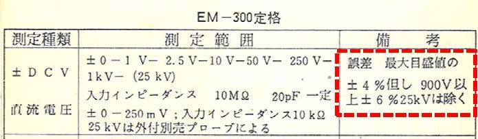
Translation of the words in the area outlined in red dashes:
See later below.
Fig. 2 SANWA EM-300 instruction manual
In Figure 2, there is a description that says: “Error: Accuracy is ±4% of full scale, but is ±6% when the voltage is 900 V or above. Excluding 25 kV.” This time I would like to explain what this means.
2. What does CLASS 2.5 mean? Chapter-1
I would like to explain meter error of an analog meter in Chapter-1 and Chapter-2. Chapter-1 shows an error when the meter displays at full scale. Chapter-2 shows the error when the meter displays at other than full scale.
You can see the “CLASS 2.5” or “~ 2.5” notation on the scale panel of the two different meters shown in Figure 3. This "2.5" indicates that there is a possibility of producing an error (allowable limit) of ± 2.5% at the maximum scale value with a 2.5-class meter. These specifications of analog instruments are described in JIS (Japanese Industrial Standards) C 1102-1 to 9 in Japan. I guess the meter error specifications are also described in the similar regulations in each country.

Fig. 3 Meaning of CLASS 2.5 meter
The meter on the left is an ammeter with a full scale (maximum scale value) of 300 mA. When this meter points to 300 mA, the reading may cause an error of up to ± 2.5%. See below for the calculations.
300 mA + (300 mA × -0.025) = 292.5 mA
300 mA + (300 mA × +0.025) = 307.5 mA
How about the meter on the right side of Figure 3? You can see “2.5” printed on the scale panel. The maximum scale value is 300V. As it is ± 2.5% of 300 V, I calculate the error shown below.
300 V × ±0.025 = ±7.5 V
In other words, it is necessary to consider the error range of 292.5 to 307.5 V with the answer of the calculation shown above (=±7.5 V), even with the indicated value of 300 V.
300 V - 7.5 V = 292.5 V
300 V + 7.5 V = 307.5 V
For our understanding so far, we considered when the displayed value is at full scale. Next, consider the error when the displayed value is not at full scale, but there may be some people who are not satisfied with this. However, because it is defined in this way, there is no choice but to try to understand it.
3. What does CLASS 2.5 mean? Chapter-2
The explanation of the first part in Chapter-1 was imaginable within the range of common sense. However, this is the point of how to consider the error when the meter does not show full scale.
Maximum value of ± 2.5% is 300 mA or 300 V is ± 7.5 mA or ± 7.5 V respectively. Let's say a meter with a full scale of 300 mA shows 100 mA. The error of the indicated value would seem to be 100 mA × (± 0.025) = ± 2.5 mA, but this is actually wrong.
The error of ± 7.5 mA calculated at the maximum value is applied to 100 mA as it is. In other words, 100 mA ± 7.5 mA = 92.5 to 107.5 mA. If the displayed value of 100 mA may actually be 107.5 mA, the error would be +7.5%, but the meter error is supposed to be considered in this way.
4. Maximum indication error is ±4% at the full scale
The SANWA EM-300 multi-meter instruction manual that I am using has an error of ± 4% of the maximum scale value. If you measure a voltage in the DC 10 V range, the error tolerance is ± 0.4 V, so you can see that the error range is 9.6 to 10.4 V.
Let's say when you use this 10 V range to repair your radio. To see if a transistor on PCB is broken or normal, we measure the junction voltage (VBE) between the base and the emitter. It should be approximately 0.7 V when the transistor is ON. However, since the voltage of 0.7 V is measured in the 10 V range, if ± 0.4 V of the maximum scale value ± 4% is added to the indicated value of 0.7 V, the minimum voltage becomes 0.7 - 0.4 = 0.3 V. If VBE is displayed as 0.3 V, instead of 0.7 V, it doesn't seem that the transistor is ON. With this, the failure of the transistor cannot be found. Still, the idea of this error is correct. In short, using this kind of voltmeter is incorrect in this case.
5. Understand the correct usage
Although the above usage is extreme, it is desirable to measure in a range that will swing the meter needle about 70 to 80% of the maximum value in order to get an acceptable accuracy in voltage and current measurements.
FB DX