
FB LAB ~Electronics Laboratory ~
Anatomy of the IC-7600 and IC-7610
The newly announced IC-7610 is the successor to the IC-7600, which had a long sales run after being introduced in 2009. We found that the circuits and technologies in the transceivers are totally different, and felt the rapid technological progress when we looked inside both transceivers.
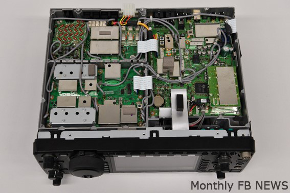
IC-7600
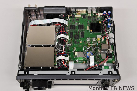
IC-7610
Oscillator circuit
See the pictures below of the oscillator circuits in the IC-7600 and IC-7610. The IC-7600 uses discrete components for coils and varactor diodes. The IC-7610 introduces a custom made VCXO (Voltage Controlled Xtal Oscillator). To achieve the high RMDR characteristics and the extremely high phase noise ratio, a very high purity of the oscillator signal is required. Therefore, an Icom custom made component is utilized, Icom engineering explained.
To produce the LO (Local Oscillator) signals for the IC-7600, a hybrid system that consists of a DDS and a PLL is used. To produce the signals for the IC-7610, a computing processing system with an FPGA is used. The FPGA system gives a very high phase noise ratio and high electronic specifications.
Left: IC-7600 VCO unit for producing the 1st LO signals
Right: IC-7610 1st LO unit for the SUB band.
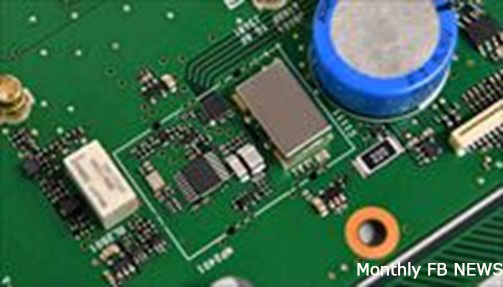
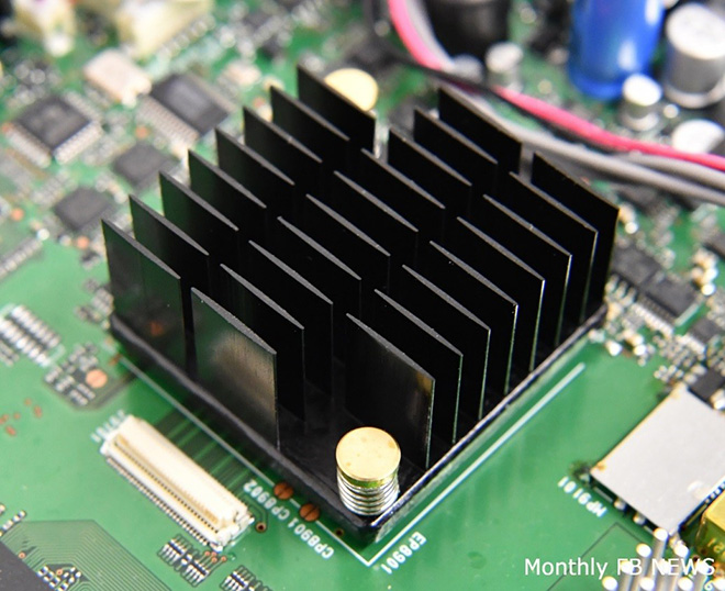
The IC-7610 Master Clock circuit. Signals produced in the circuit are directly distributed to the D/A converter for TX, the A/D converter for RX, and the FPGA.
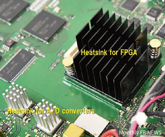
We can see the heatsinks for the IC-7610 FPGA and the A/D converters.
RX circuit
We can see the mixer circuit and roofing filters on the left picture below for the IC-7600. There is no mixer circuit that causes non-linear distortion on the IC-7610 shown on the right, because the IC-7610 utilizes the RF direct sampling method, and RF signals are directly converted into digital signals for processing in the FPGA (Field Programmable Gate Array).
The IC-7610 circuit does not have roofing filters installed because there is no distortion produced in the IF stage due to digital processing, and a narrow filter is not required.
The IC-7600 Mixer circuit for the main and sub bands of RX. We can see roofing filters on the right side of the picture.
The image rejection filter in the picture to the right.
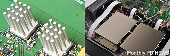
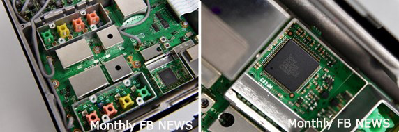
IC-7610 Left: A/D converter for RX
Right: DIGI-SEL units are installed in shielded boxes
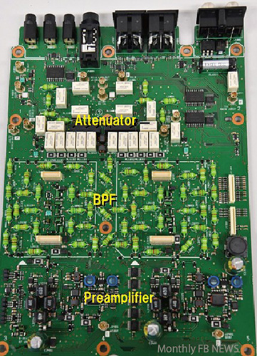
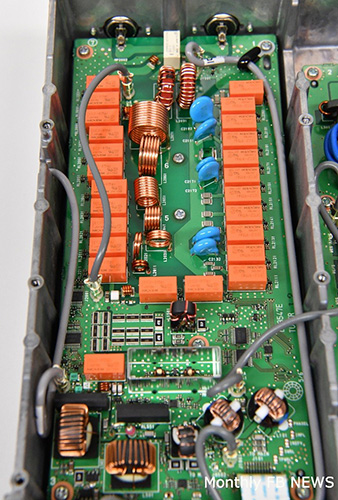
The IC-7610 RF unit. We can see that the attenuator circuit, BPF circuit, Preamplifier circuit are independently installed for the Main and Sub bands.
Scope
Signal processing from the received RF signals to displaying them on the real time scope was complicated in the IC-7600 because the transceiver used the superheterodyne system, and signals are processed in an analog system such as a 1st mixer of IF → BPF for the scope → 1st mixer of the scope → Crystal filter → 2nd mixer → A/D converter → DSP → Real time scope. These complicated processes are digitally processed with an FPGA on the IC-7610, as shown in the picture below, and the circuit looks very simple.

<IC-7600>Left: 1st mixer for 64.455 MHz.
Right: DSP chip for controlling the spectrum scope
The IC-7610 FPGA digitally processes signals, and the number of components is few.
TX circuit
One of the transmitting signals of the IC-7600 is produced by the DSP, and the signal is finally converted to transmit signals through a mixing circuit. Therefore, LO (Local Oscillator), mixers, and filters are needed. However, the signals from D/A converter in the IC-7610 become the transmit signals directly, without the circuits mentioned above. This makes less unwanted signals, and it means the IC-7610 transmits clean signals.

<IC-7600>Left: Transmit circuits
Right: PA unit and LPFs
<IC-7610>Left: D/A converter
Right: PA unit
<IC-7610>LPFs for TX
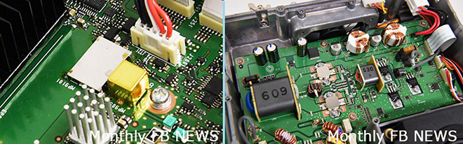
Auto antenna tuner
Both the IC-7600 and IC-7610 have an internal antenna tuner. The one for the IC-7600 consists of coils and variable capacitors, and the variable capacitors are driven by fast speed servo motors. The one for the IC-7610 consists of coils similar of IC-7600’s and mechanical relays for RF. This makes for a much faster tuning speed.
<IC-7600>Left: Control unit for the antenna tuner
Right: Tuning part by variable capacitors (Two servo motors can be seen in the front.)
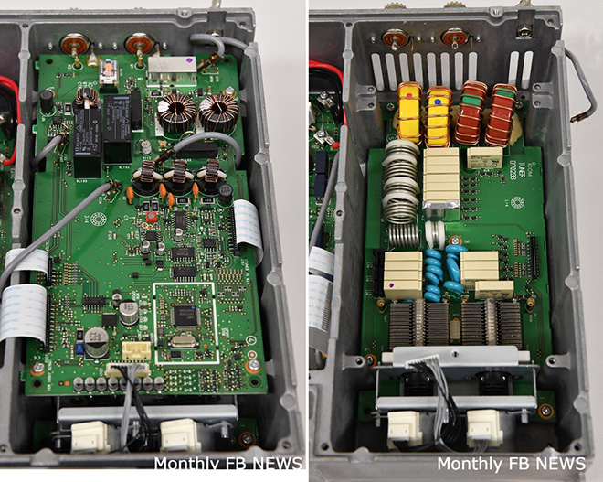
The antenna tuner unit of the IC-7610 does not have two separate units, like the IC-7600 has. It has only one unit for both the control part and the tuning part, as shown in the picture.
Speaker
The speaker of the IC-7600 is simple, but audio quality has a good reputation among users. Output signal quality is very important. Even if the transceiver receives a very weak signal, but the output of the audio quality is not good as fidelity, and readability becomes lower, and we may not communicate well. The IC-7610 introduces an Icom custom made closed type speaker housing, and cushions are attached outside of the speaker to prevent the audio from resonating with the transceiver covers.
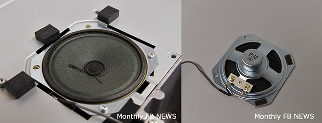
The IC-7600 speaker is securely installed in the chassis to provide a high audio quality.
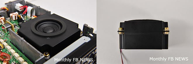
The large magnet speaker in the IC-7610 is mounted in a custom made closed type housing, and insulators are used to provide high audio quality.
Others
The IC-7600 Main CPU is installed on the logic unit. The logic unit is located just behind of the front panel.
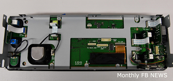
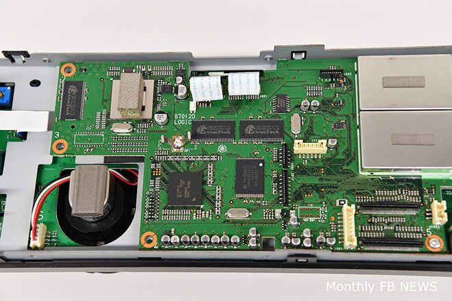
The picture above is the back of the IC-7610 front panel. Most of circuits are built into the Main unit, so that the front panel unit is clean in design.
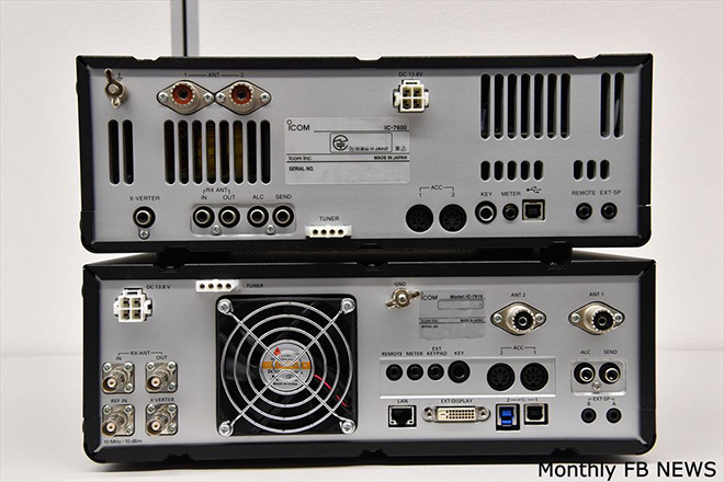
Above: IC-7600
Below: IC-7610 The IC-7610 has an external display connector, two types of USB connectors are additionally installed for expanding functions. Two pairs of RX-ANT (BNC) connectors are added for user customizable antenna connections.