
Technical Trivia by Dr. FB
What is the Triplexer?

Dr. FB
In recent years, 1200 MHz FM handheld transceivers have been sold by Alinco in Japan. However, all-mode VHF/UHF/1200 MHz transceivers have not been available from radio manufacturers for a long time. I don't know if it was the reason, but I could hardly hear any signals on the 1200 MHz band.
After the Icom IC-9700, 144/430/1200 MHz Triband transceiver was introduced, we can hear FM, SSB, and CW signals on the 1200 MHz band, especially on the weekends. The 1200 MHz band has become a bit lively.
In the meantime, I have heard about a “Triplexer” or a “Triband antenna” in local lag-chews. This time, I will explain about the triplexer. In the explanation, you will see difficult words such as “Insertion loss” or “Isolation” and “decibel (dB),” but I would like to explain these words simply.
1. What is a triplexer?
In “triplexer,” you can see the root word “tri,” which means “three.” In this triplexer, the “three” are the 144, 430, and 1200 MHz bands.
The photo in Figure 1 is of a CFX-431 Triplexer from COMET Co., Ltd., a Japanese antenna manufacturer. There is one connector (COM) on one side of the triplexer, and three cables for the other bands on the other side. Neither are a specified input or output connection, as they can be used in both directions.
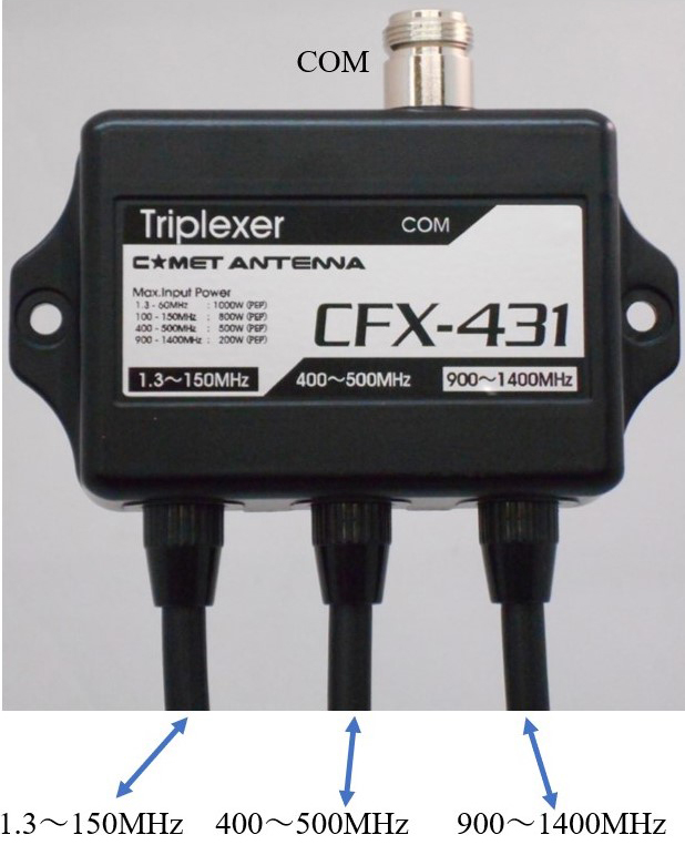
Figure 1. Comet triplexer CFX-431 (photographed by COMET Co., Ltd.)
In the CFX-431 triplexer manual, there are three use examples, illustrated in Figure 2.
The Icom IC-9700 can operate on 3 bands, and has three independent antenna connectors for 144 MHz, 430 MHz, and 1200 MHz on the rear panel.
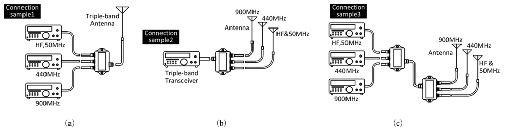
Figure 2. Example of triplexer usage (extracted from the instruction manual of COMET CFX-431)
If you have a triband antenna, and a triplexer, an IC-9700 can be operated with the simple connections shown in Figure 3.
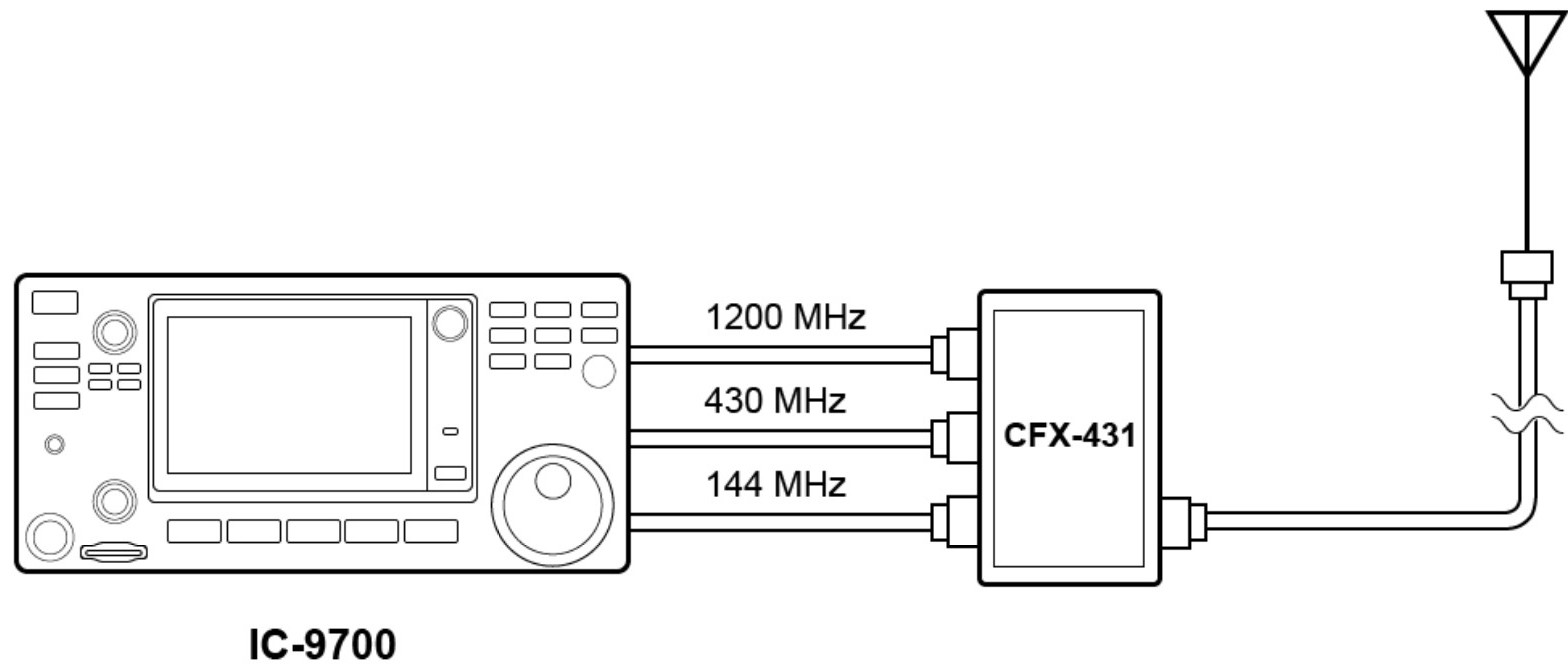
Figure 3. Connection example of an IC-9700 and a CFX-431
2. Triplexer inside and its circuit
I removed the back cover of COMET CFX-431 Triplexer and looked inside. Only coils and capacitors are mounted on the board, as shown in Figure 4.
Figure 5 shows the circuit diagram of the actual product. From this circuit diagram, you can see that three filter circuits are configured on the board. Figure 6 shows a block diagram of the circuit diagram.
Inside, it seems that a sufficiently large area of the ground pattern is secured on the PCB so that sufficient performance can be obtained, even in the very high frequency bands from the VHF bands to 1200 MHz. As you can see, the circuit components are firmly soldered by hand. Perhaps the characteristics of each filter are carefully and manually adjusted at the factory.
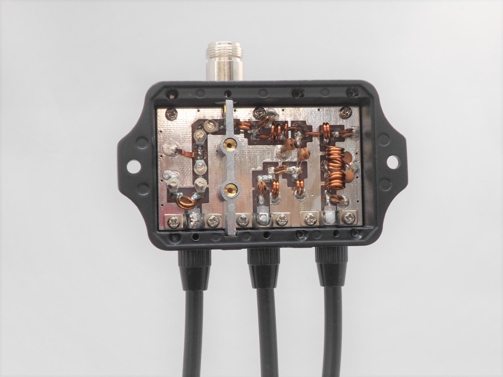
Figure 4. Internal photo of COMET CFX-431 ((photographed by COMET Co., Ltd.)
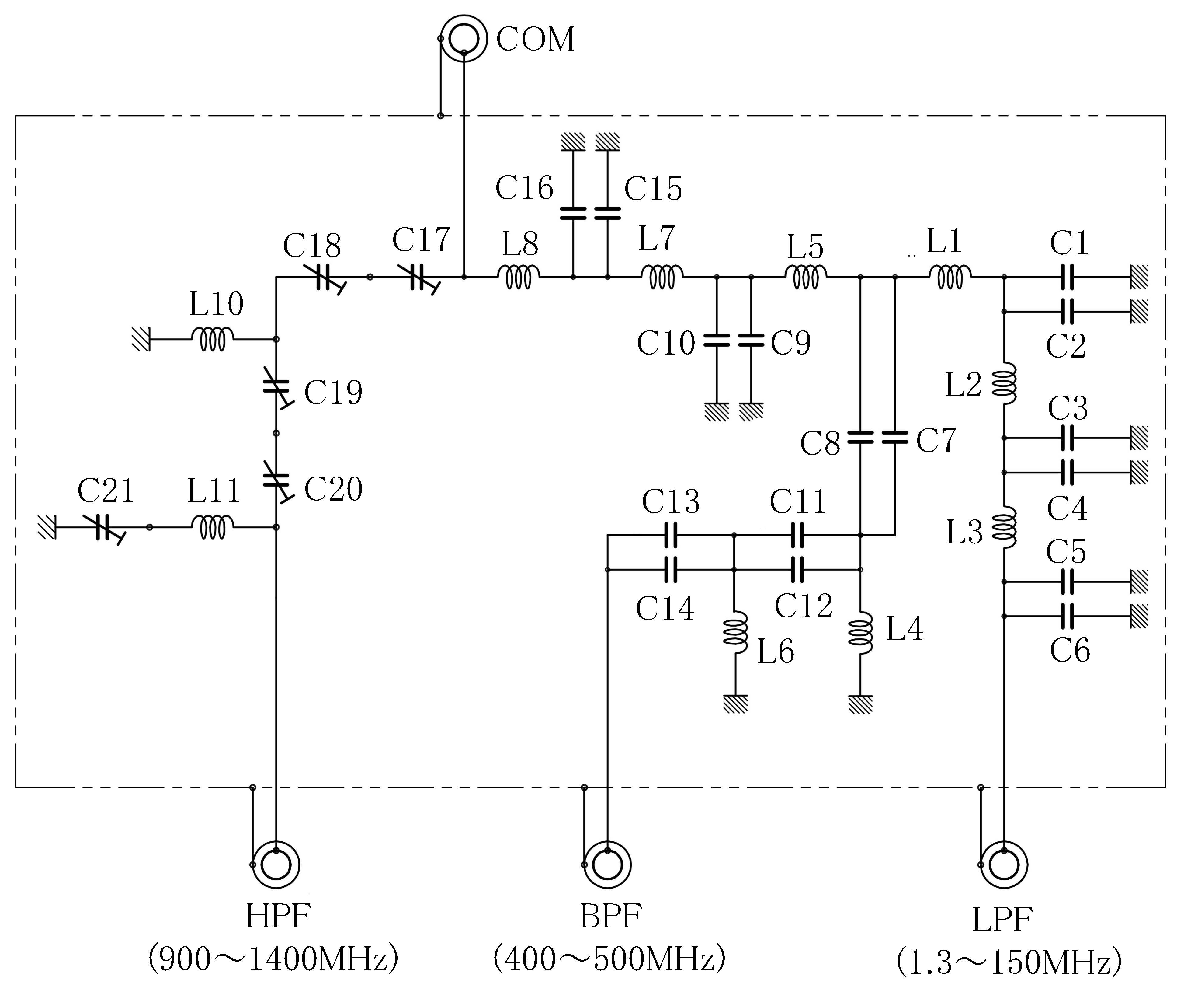
Figure 5. Circuit diagram drawn from the actual product
(Part numbers are printed appropriately by the editorial department)
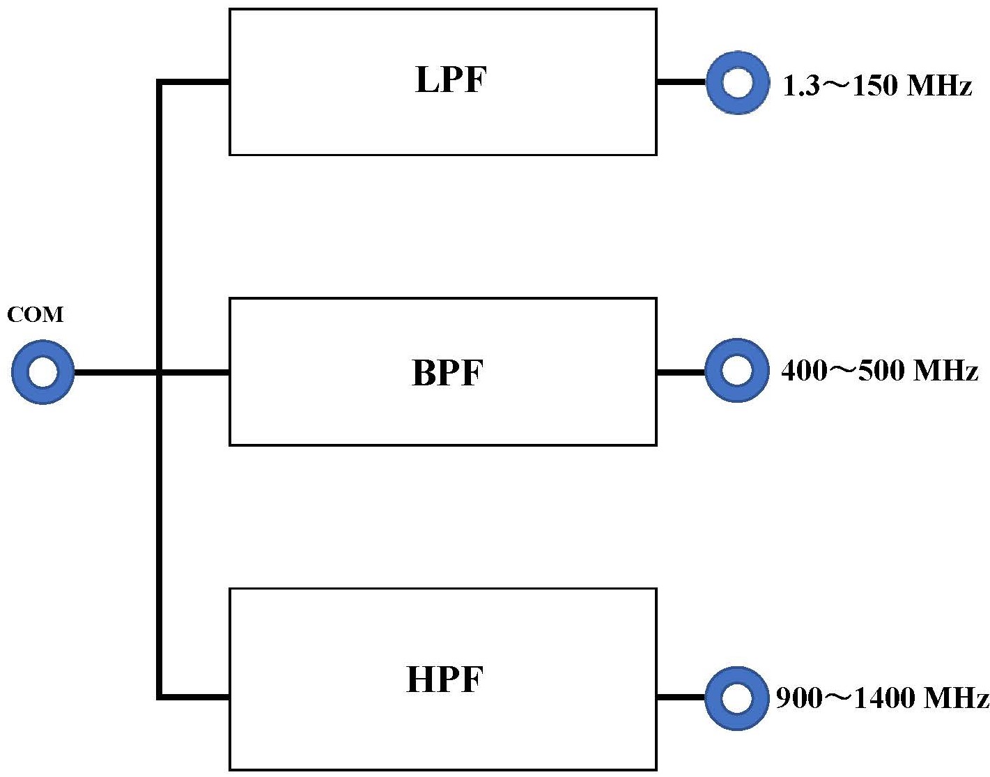
Figure 6. Block diagram of the triplexer (CFX-431)
3. Circuit theory of operation
Between the terminal of 1.3-150 MHz and the connector of COM consists an LPF (low-pass filter), and only the frequency below 150 MHz is allowed to pass. On the other hand, a BPF (band pass filter) is configured between the COM connector and the 400-500 MHz terminal, and only the frequency between them is passed. Furthermore, between the connector of COM and the terminal of 900-1400 MHz configured an HPF (High Pass Filter), and only the frequency of 900 MHz or higher passes.
There is no distinction between the input and output of the COM connector and the terminals of each band, and the impedance is 50 Ω when viewed from either side. It is a very convenient item for hams who operate multi-band.
The triplexer has 3 connectors for the 3 bands. “If only two bands are used, it is recommended to terminate the connector of the non-used band with a 50 Ω dummy load,” as stated in the instruction manual.
4. The CFX-431 Specifications
A copy of the instruction manual for COMET triplexer CFX-431 is attached in the Figure 7. Figure 7 (b) is an enlarged view of the part drawn by the red lines in the instruction manual. There are two notable specifications. One is the insertion loss and the other is the isolation mentioned at the beginning.
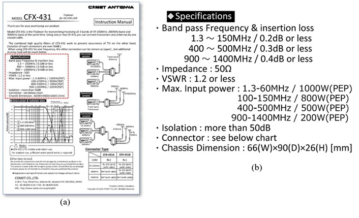
Figure 7. Copy of CFX-431 instruction manual (provided by COMET)
(1) Insertion loss
The insertion loss specification is 0.2 dB or less within the pass frequency range of 1.3 to 150 MHz. The smaller this number is, the less loss the triplexer has. You can see how small 0.2 dB is in the calculation shown below in Figure 8. In the calculation, if 10W is input, 9.55 W will be output. The difference, 0.45 W, is the insertion loss.
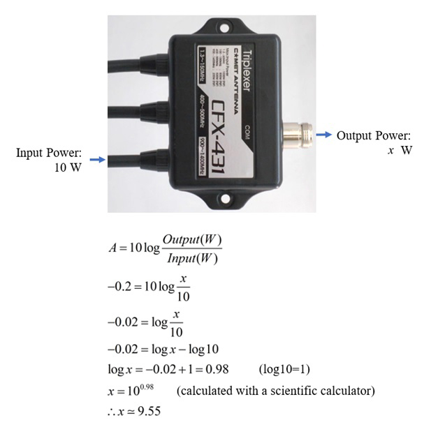
Figure 8. Insertion loss of 0.2 dB
(2) Isolation
According to the specifications, isolation is described as 50 dB or more. This isolation may be easy to understand, for example, the isolation of each circuit in the 144 MHz, 430 MHz, and 1200 MHz bands. When a 144 MHz signal is input into the terminal, most of the signal is output from the COM connector on the opposite side, but it is output from a different terminal due to the coupling of the internal circuit. Therefore, the larger the number of this isolation, the better the separation, and the leakage power is extremely small. The result of calculating shows the 50 dB isolation is only 0.1 mW for the 10 W input.
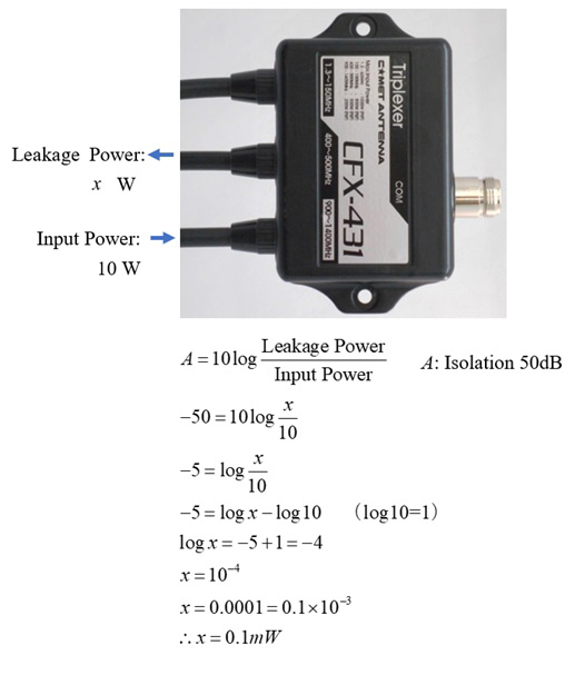
Figure 9. Isolation of 50 dB
5. Actual operation using the triplexer
I have an IC-9700 and operate it with a triplexer and a 3-band antenna, as shown in Figure 10 below. I can watch for local stations by scanning in the SUB band, even while operating 1200 MHz on the MAIN band. To use a triplexer, a tri band antenna, and a tri-band transceiver, the coaxial cables are combined into one, and the shack installation is clean.
FB DX