


It’s Fun to Build Electronics Circuits!
Speech Compressor
In the operation of amateur radio, I think that we often want to transmit radio waves as far as possible. So, we thought about a speech compressor in order to get more talk power in the SSB mode.
The ratio of the peak level to the average level of the audio signal is large in SSB. If the power is limited at the peak level, the average level will drop, and we cannot expect to get a higher talk power.
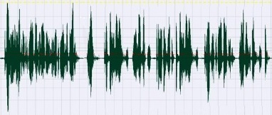
Figure 1. An example an audio wave form
Therefore, it is a speech compressor that reduces or compresses the peak level a little and increases the average level for communication. If the peak level is processed, the waveform will naturally change, and signal distortion will occur. When using a speech compressor, the trade-off between distortion and increased average power can be adjusted.
There are various ways to reduce the peak level of the audio signal, but this time, let's consider the simplest method using diodes. Looking at the forward characteristics of the 1S2787 silicon diode, the forward current rapidly increases at 0.6 V and at temperature of 25°C (77 °F) in the graph shown below.
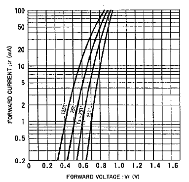
Figure 2. Forward-biased diode characteristics
I experimented with a simple circuit that cuts the peak level of the signal using these diodes.
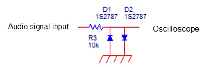
Figure 3. Signals are clipped by the diodes
The input signal appears on the oscilloscope as it is up until the diode’s forward voltage is reached, but at higher voltages it is clipped by diodes. The waveforms are shown below.
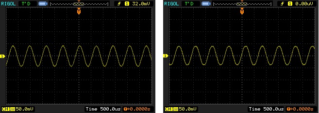
Figure 4. When the input signal is small (left input, right output)
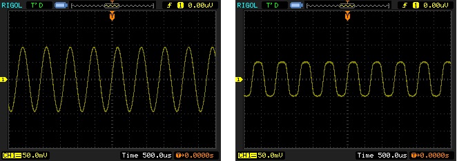
Figure 5. When the input signal is large (left input, right output)
If the input signal is lower than the forward voltage, the signal appears on the oscilloscope unchanged, but if the signal level becomes higher than the forward voltage, the signal is clipped and suppressed. In the experimental circuit, the current flowing through the diode dropped, the forward voltage became approximately 0.5 V, and the signal level became about 1 V p-p. As you can see the characteristic diagram of the diode in Figure 2, the voltage clip changes when the temperature changes, but I don't think that it is usually noticeable in the usage conditions around the normal temperature.
The circuit of the speech compressor is clipper circuit as shown below.

Figure 6. Speech compressor circuit
The signal input from the microphone terminal (Mic) is amplified by IC1A for a gain of 27 dB by adjusting the input level with potentiometer R6, but the audio voltage applied to the diode changes with R6, so the level is clipped by R6.
OP-Amp IC1A generally requires (+) and (-) voltages. In these circuits, since the IC power supply is a single power supply, it is necessary to use the midpoint of the power supply as a reference, which is made with R4 and R5. The voltage is fed to the (+) terminal of the non-inverting input of IC1A. Therefore, the output of IC1A also operates based on the midpoint voltage, so the amplitude limiter circuit composed of R3, D1, and D2 also uses the diode midpoint as the voltage midpoint. IC1B is a buffer amplifier to prevent the diode from being loaded as much as possible.
A signal whose amplitude is clipped is slightly distorted, and a lot of harmonics are emitted at the same time. Unnecessary audio harmonics makes the signal bandwidth wider, which causes problems to an adjacent operating station. Therefore, harmonics need to be removed. I think that the transmitter usually has a band-limiting circuit, but just in case I put an LPF in this circuit as well.
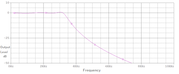
The circuit composed of IC2A and IC2B, and R9 to R13, and C5 to C10 is an active LPF circuit, which reduces unnecessary harmonics above 3.1 kHz. The cutoff was chosen to be 3.1 kHz because I wanted to keep the bandwidth a little wider, and I wanted to use the circuit I was already using.
The result of simulating the characteristics is as follows.
This speech compressor circuit originally does not require gain, but part of circuit shown in Figure 6 has a gain in signal processing, the clipped level of about 1 V p-p is finally adjusted to near the microphone level with R14 and R15. The power supply uses a 3-terminal regulator IC chip. The input voltage of the IC is 10 V to 15 V, and the output is stable at 5 V.
These are the circuit components mounted on a 52 mm x 70 mm (2 in x 2.8 in) universal circuit board.
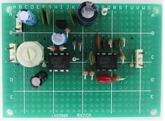
Figure 8. components are mounted in a universal circuit board
When assembled and checked, it was confirmed that the peak level was clipped at 1 V p-p as in the first experiment, and that it was working as intended.