


Special Article
The world of 5.6 GHz enthusiasts.
The current state of the 5.6 GHz band and how to enjoy it.

Antenna system
In the 5.6 GHz band, parabolic antennas are commonly used in a fixed and portable operations. In moving mobile stations, a whip antenna is commonly installed in a vehicle and the fixed station chases the mobile station with a movable parabolic antenna.
In an operation at home as a fixed station, not only the horizontal rotator, but also the elevation rotator will be mounted on the mast corresponding with rain scatters. I have heard that he sometimes points the parabolic antennas straight up to protect them from strong wind in bad weather conditions. The horizontal installation of the antennas requires special attention, and the installation must be adjusted so that all the antennas are facing the same direction, and the actual orientation of the antennas is inline with the orientation indicated by the rotator.
This precise adjustment of antenna orientation enables us to determine from a direction of the antenna when the radio propagation is a direct wave, or that the communication is due to a reflected wave from a particular mountain.
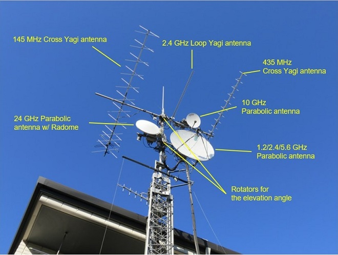
JA1OGZ Antenna group at Mr. Kaneko's house
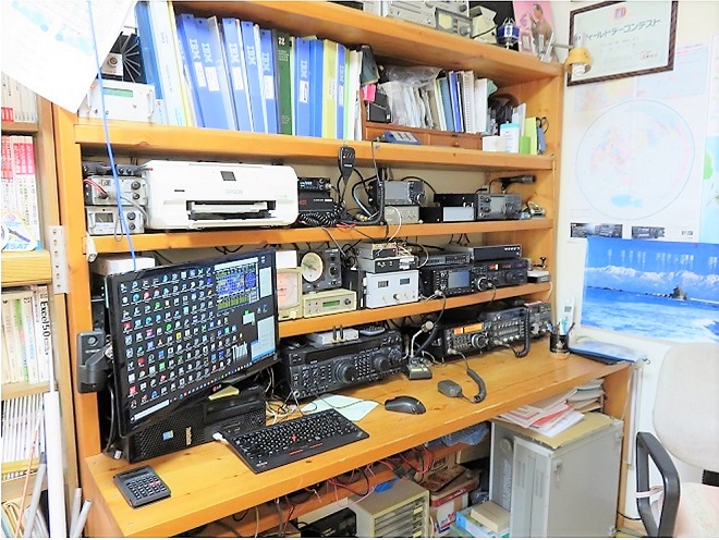
JA1OGZ, Mr. Kaneko's radio shack
Various propagation in the 5.6 GHz band
The following are the four main types of propagation in the SHF band including the 5.6 GHz band.
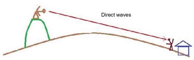
(1) Direct waves
Basically, direct waves in the SHF band such as 2.4 GHz, 5.6 GHz, and 10 GHz bands, can reach anywhere in a line-of-sight range. The propagation loss is smaller compared with the antenna gain and output power.
Propagation distance of radio waves in the SHF band can be calculated using the formulas below. If the antenna elevation of each 2 station is h1(m) and h2(m), the formula (1) is used, but if one station is set at the top of a mountain and one station is set at plains, the formula (2) can be used as an approximation to find the line-of sight distance that can be communicated.
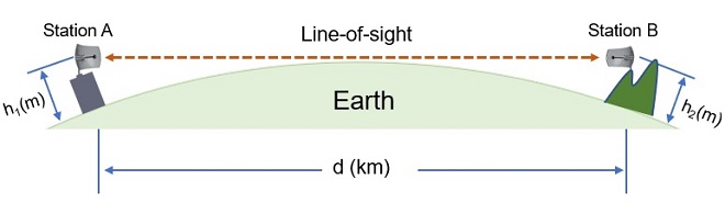

For reference, if one station sets up an antenna on a mountain 1,000 meters above sea level and transmits a signal from there, and the other station is operating on level ground, the possible communication distance can be substituted into formula (2), d=133 km.
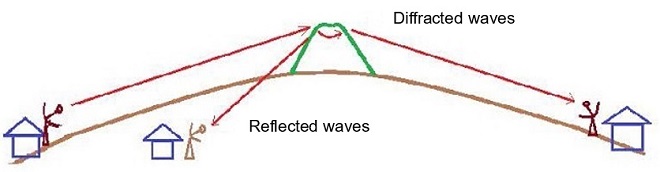
(2) Diffracted waves and reflected waves
SHF radio waves can reach unexpected places due to diffraction and scattered reflections. One of an amateur radio group I visited, who live near Tokyo, often use reflections from mountains, skyscrapers in downtown, and scattered reflections from distant mountains to communicate with each other. Especially in the winter, there are times when the reflections are different due to changes the surface of mountains covered with snow and the humidity on the surface, making the propagation different depending on the season.
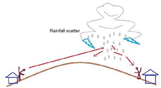
(3) Rainfall Scatter
Rainfall scatter is expected to allow communications with areas that are normally unreachable. A communication with hearing of buzz sounds is possible through rainfall scatter, which is from Tokyo area to places where 100 to 200 km away. In the 10 GHz band, the attenuation of radio wave propagation due to rainfall becomes larger, and there is a balance between the strength of scattered waves and rainfall attenuation. To take advantage of this, we can use an elevation angle rotator to receive stronger signals.
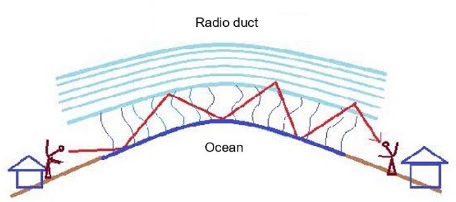
(4) Radio duct (A duct structure like a waveguide propagation path)
It is also possible to communicate using the radio ducts as in the VHF and UHF bands. In the 5.6 GHz and 10 GHz bands, a radio duct especially called the ŌĆ£Japan Sea Radio DuctŌĆØ has been recorded between two places in the Japan sea area for distance of 710 km in the FM mode.
Actual operations of the 5.6 GHz band
When I visited Mr. Kaneko's shack, I was able to observe the actual communications. The person on the other end was JA7JJN, Mr. Yanagisawa, who is well known on TV. They were talking about their antenna direction. The azimuth of Mr. Kaneko's antenna was 227 degrees, and the azimuth of the other station's antenna was 210 degrees, so the signal strength was 59+ even though their antennas were not directly facing each other. When I asked Mr. Kaneko about it, he said, "At this angle, the propagation is due to the reflection from the mountains far to the west of Tokyo. According to the simulation software, the distance between two stations was about 35 km in a straight line, but due to the topography, they could not see each other directly, so the transmission was made by reflection from a distant mountain. I was even more surprised to hear that the round trip propagation distance would be about 100 km.
According to Mr. Kaneko, the recent announcement on Icom's website that the development project for 2.4 GHz and 5.6 GHz has started and has raised expectations among his amateur radio colleagues. Since there are no commercially available radios in this band and only a few types of transverters, I was told that there are probably many people who operate in the SHF band and contest enthusiasts who operate on multiple bands.
Finally, I would like to express my deepest gratitude to JA1OGZ, Mr. Kaneko for taking time out of his busy schedule to interview and for providing image data, JA7JJN, Mr. Yanagisawa for communicating with Mr. Kaneko on the day of the interview, and JA0RUZ Mr. Sekizaki and JH1AOY Mr. Tamagawa for providing other image data. TU