


Short Break
Making a straight type AM radio using a TA7642 IC
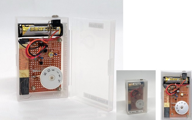
Finished the straight radio built into a plastic case
Most of our receivers use the well-known superheterodyne system that is the most common receiver configuration. You can find many articles on electronic projects in a net search. The superheterodyne system is a great receiver for amateur radio. However, it is quite difficult to build, and we hesitate to do so.
Although its performance is far from that of such a receiver, I will make an AM radio with a useful IC for medium wave listening, which I will introduce here.
The part name of this IC is TA7642, and it has only three leads. Since the TA7642 is an IC, it does not operate without batteries like germanium radios, but a small number of external parts are required, and can be used to make a radio that is practical. In this article, I will use the TA7642 and enjoy making a radio with a little experimentation.
Three terminal IC for the reception of medium wave AM signals
TA7642 looks like a transistor, but it's actually an IC that has three terminals. The IC was designed for a medium wave AM radio and the shape is shown in Figure 1.
In the photo, the 2SC945, the 2SC1815 and the TA7462 are all available in a package style called TO-92. However, TA7642 looks slightly smaller than the other two transistors. When measured with calipers, it is indeed smaller than the others, but it is within the dimensions of the TO-92 specifications. The size is not important for the performance of this radio, but this is just for your information.
The IC has an RF amplifier circuit and a detector circuit installed in its package. According to the IC's datasheet, the minimum DC power supply is 1.2 V and the maximum is 1.6 V, so it can be said that this IC is especially designed to operate on a single 1.5 V AA size battery.

Figure 1. TO-92 size appearance
Discussion of a sample circuit using a TA7642
The datasheet of the TA7642 can be obtained through a net search. The sample circuit described in the datasheet is shown in Figure 2. The transistor shown in the sample circuit diagram is difficult to obtain, so I used a 2SC1815, which is a popular NPN transistor, and is for audio frequency general purpose amplifier applications. There is no description of the LC resonant circuit connected to the input side of the IC in its circuit diagram, so I tried to calculate it using the formula shown below. By changing the resonant frequency of this LC resonant circuit, the AM broadcast band can be tuned.
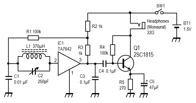
Figure 2. Sample circuit described in the TA7642 datasheet.
Let us calculate the value of L (inductor) to match 250 pF using the formula for a resonant circuit.
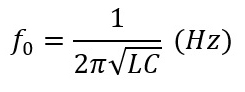
The frequency range of AM radio broadcasting in Japan is 526 kHz to 1,665 kHz. From the above formula, I can see that increasing the capacitance of the variable capacitor lowers the resonant frequency, and decreasing the capacitance raises it. Assuming that the resonant frequency when the capacitance of the variable capacitor is set to the maximum value of 250 pF is 526 kHz, which is the lower limit of the AM radio frequency range, the value of inductor is calculated to be 370 ┬ĄH.
Based on the calculated value of the inductor, I calculate the resonant frequency with the minimum value of 15 pF. The resonant frequency f0 is 2,136 kHz, which is much higher than the upper limit frequency of AM broadcasting, but since it is covered, I proceeded. Figure 3 shows the capacitance of the variable capacitor and the resonant frequency calculated.
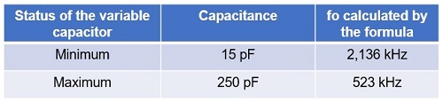
Figure 3. Capacitance vs. resonant frequency of variable capacitor (L=370 ┬ĄH)
Building an AM radio using a sample circuit diagram
As you can see from the circuit diagram in Figure 2 above, the configuration of the receiver is a straight radio without a frequency conversion circuit. IC1 performs the RF amplification and detection. The IC outputs the detected signal, but it is only enough to drive a crystal earphone. Therefore, an AF amplifier with a single transistor is added to drive the earphones, headphones, or speaker. When the headphone or speaker is connected, a voltage of 1.5 V is applied to the collector of Q1 through a moving coil. The circuit does not work with a crystal earphone because the DC power is not applied to the collector of the transistor through the crystal earphone. The original sample circuit for this IC does not have a power switch. You may want to add it if necessary.
(1) Making a ferrite rod antenna
The first step is to make an inductor to use with a variable capacitor as the resonant circuit. The inductor is wound on a bar-shaped ferrite rod. This can also be used as a directional antenna. It is called a ferrite rod antenna or ferrite bar aerial because of its rod/bar shape. To make a rod antenna, enameled or polyurethane wire is wound around the ferrite rod dozens of times, but without a measuring instrument, it is difficult to know how much to wind to get 370 ┬ĄH. At the end of the datasheet for this IC, there is information on how to make the inductor. According to the information, "The coil is made by winding 0.315mm (30SWG) on a 100x10 mm ferrite bar for about 55 turns.ŌĆØ The information of the inductor in this experiment is shown in Figure 4.
The inductor shown in Figure 4 was made using an impedance bridge to the calculated value of 370 ┬ĄH.
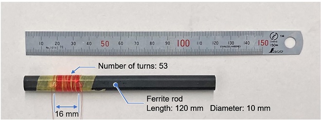
Figure 4. Appearance of the rod antenna.
This rod antenna is fine for experimenting on a breadboard, but if you want to install this radio into a small plastic case, you need to wrap it around a smaller ferrite rod. As a result, I decided to wind it on the smaller ferrite rod shown in Figure 5. The number of turns is 87, and the inductance is approximately 370 ┬ĄH, which is the same as the ferrite rod antenna shown in Figure 4.
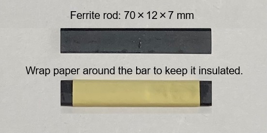
Figure 5. Making a ferrite rod antenna using a smaller size ferrite rod
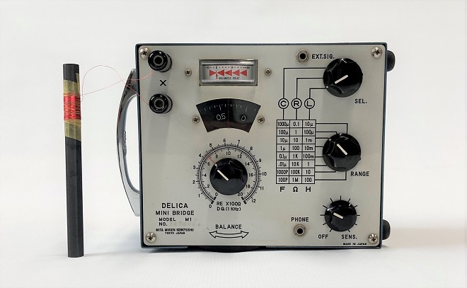
Figure 6. Measuring the inductance of a coil with an impedance bridge
(2) Experiment with the sample circuit on a breadboard
Since this is a simple circuit, it can be built on a universal board as shown in Figure 7 (right), but since the purpose is to conduct experiments, it is first built on a breadboard as shown in Figure 7 (left). When the crystal earphone is connected directly to the output of IC1 (TA7642), signals of AM broadcasting stations can be received like a germanium radio. The AF amplifier consisting of Q1 (2SC1815) is built as per the sample circuit to complete the AM radio. Since the bar antenna is directional, the volume level of the received station changes as the bar antenna is rotated.
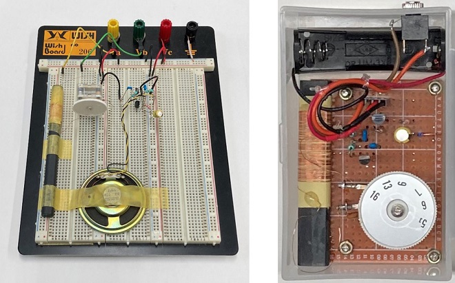
Figure 7. he straight radio
The only stations I could receive were JOBK (NHK Radio 1: 666 kHz/100 kW), JOBB (NHK Radio 2: 828 kHz/300 kW), and JOUR (Radio Osaka: 1314 kHz/50 kW). JOBB is so powerful and signals from stations JONR and JOOR are suppressed with that powerful station signal.
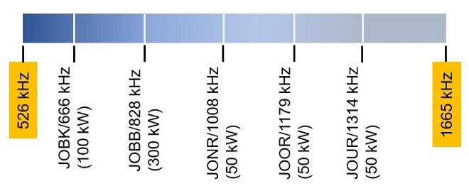
Figure 8. AM broadcasting stations in Osaka Japan
AF volume control pot added to the sample circuit
When earphones or small headphones are connected to the jack in the AF amplifier circuit configured in Q1, radio reception is possible. As shown in Figure 7 (left), I connected a speaker instead of earphones to the circuit of Q1, but the level was so small. The AF amplification circuit of Q1 is not enough to drive the speaker.
So, I connected the AF amplifier unit that I made in "Building an audio amplifier using an LM386 IC chip" in the February 2021 issue of the Short Break to the output terminal of Q1. The volume was too loud and rather distorted, so I added a variable resistor (VR1) between IC1 and Q1 to adjust the detected volume level, as shown in Figure 9.
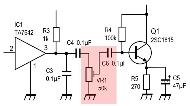
Figure 9. AF volume control pot added to the circuit
Summary
The transmitting antennas of AM broadcast stations are all located within a 20 km range from where I was. So, the field strength against each broadcasting station is very strong. The ferrite rod antenna alone is sufficient to receive signals. However, in some areas, the signal strength is weak, and reception may be difficult. In this case, connecting a wire as shown in Figure 10 improves the reception.
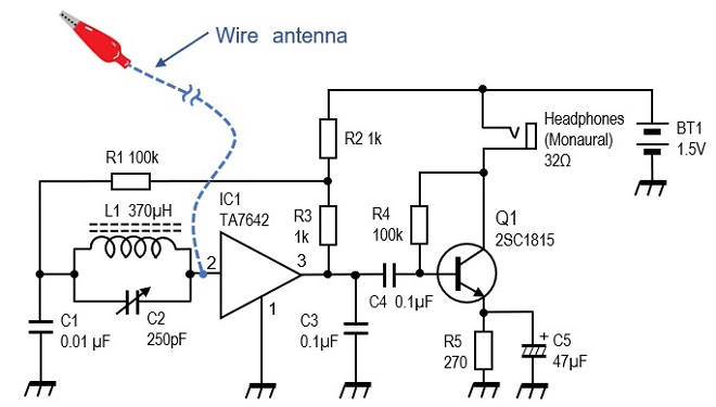
Figure 10. Connecting a wire antenna
With the sample circuit shown in the IC datasheet, the selectivity was insufficient, and I could not receive each of the five AM stations separately. I think one of the reasons is that the signal of NHK Radio 2 is too strong’╝ÄI think there is also the issue of the Q of the LC resonant circuit, which affects the selectivity.
The inductance of the inductor used in the LC resonant circuit was also measured by a nanoVNA, but the result was different from the one I measured with the impedance bridge, and the inductor made by the nanoVNA could not receive the signal well. This is also an issue, and I would like to try to improve the selectivity and make a HF low band CW receiver based on this schematic in another article.
CL
Short BreakŃĆĆbacknumber
- How many colors do you see when a colored disc is rotated at high speed?
- Making a dual Positive/Negative voltage power supply in a single box, for experiments
- Building of an RF Volt-Ammeter for QRP operation
- White noise generator project
- One day electronics project ŌĆō Making a simple antenna tuner for QRP operations
- Can the RHM12 portable antenna be matched with a bicycle body on HF?
- Making an ŌĆ£ON AIRŌĆØ lamp using LM358
- Making a simple anemometer
- Making a sound machine say ŌĆ£Good morning. Thank you for everything.ŌĆØ
- Electronics project for the 10 MHz reference signal generator (2)
- Electronics project for the 10 MHz reference signal generator (1)
- Making a straight type AM radio using a TA7642 IC
- About splitters
- Electronics project for FB NEWS: Making a decoration light string
- Making a Simple Electric Field Strength Meter
- Building a simple QRP power meter
- Building a 20 Amp electronic DC load device using an N-channel MOSFET for the load
- Building an automatic backup power switching unit
- Overvoltage protection device using LM358: Part 2
- Building an Over Voltage Protector: Part 1
- Making a 50 MHz monoband MLA without a variable capacitor
- Making a 50 MHz monoband MLA.
- Let's connect a computer headset to the IC-705
- Building a microphone selector
- Building an audio amplifier using an LM386 IC chip
- An External Keypad for Icom Transceivers
- After all, is the receiver good for Up-conversion?
- Find the gain of the stack antenna
- The mystery of controlling the microphone and PTT with only two wires
- RFID tag