


Special SHF Article 4
IC-905 Specifications Revealed at the Icom Fair
On December 18, 2022, just before the end of the year, the Icom Fair was held at the Icom Narayama Laboratory in Nara Japan. The state of emergency for coronavirus infection has been lifted, and the spread of the virus has calmed down to a certain extent, so the fair was held, but under thorough measures to prevent infection. Despite the cold weather with northerly winds, the fair was blessed with clear skies and attracted more than 500 visitors according to Icom's domestic sales department. That made it the largest event ever held by the company among those in which other companies related to amateur radio also exhibited their products.
Overview of the IC-905 as seen at the Icom Fair
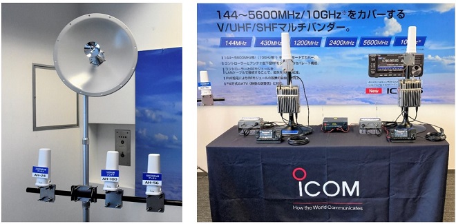
The IC-905 and antenna display at the Icom Fair
The IC-905 had already been shown to the public at last year's ham fair in Tokyo and other ham events, but many visitors were at the Icom Fair to see it and to get updated information since then. Among them, the price and release date were of interest. According to the on-site staff, the main unit is priced at about JPY400,000 and the 10 GHz transverter at about JPY150,000, which is a tentative price but gives a general idea of what it will cost. The product will be released around spring of 2023.
Features of IC-905
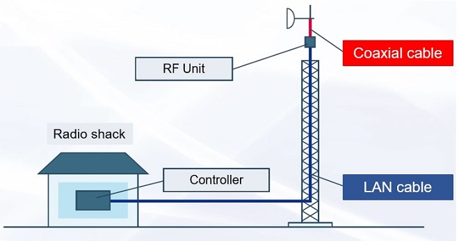
The IC-905 is capable of transmitting and receiving in the 144 and 430 MHz band, but its most notable feature is the UHF and SHF bands above 1200 MHz. It is already well known that at such high frequencies, the loss caused by coaxial cables is significant, and this has a significant impact on transmission and reception. In the business world, at these higher frequencies, called microwaves, transmission between the radio and antenna is done using waveguides instead of coaxial cables. But since this is amateur radio, the IC-905 uses the company's wireless LAN technology for this part of the system.
Information provided by Icom Inc.
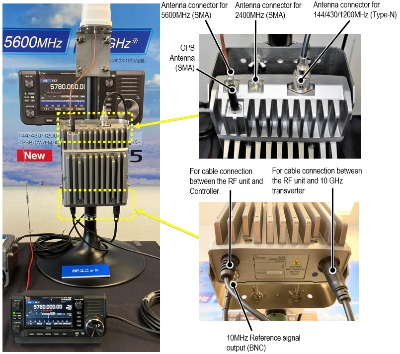
In short, the RF circuits for transmitting and receiving are installed as the RF unit directly underneath the antenna, and the RF unit is connected to the control unit with a LAN cable. However, the coaxial cable is only a few tens of centimeters long, so the loss seems to be minimized.
Controller unit of IC-905
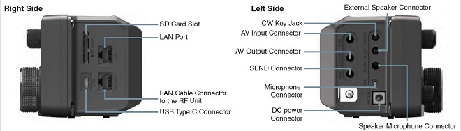
The controller housing of the IC-905 is based on the IC-705 and has the same external dimensions. As mentioned earlier, a LAN cable is used to connect the controller to the RF unit installed directly underneath the antenna, so the controller is also equipped with a LAN cable connector. Other input/output terminals are basically the same as those of the IC-705, including AV input/output terminals for UHF and SHF specific operation modes.
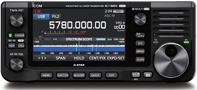
Photo: Excerpted from pre-release information of Icom Inc.
Information provided by Icom Inc.
RF unit of the IC-905
The RF unit is mounted directly under the antenna to minimize the RF loss generated by the coaxial cable between the antenna and the RF unit. The RF unit itself is made of aluminum die-cast and appears to be a heavy-duty structure. Since the unit is to be installed outdoors, it is all-weather waterproof, so there is no need to worry about rain and wind.
Frequency stability of the IC-905
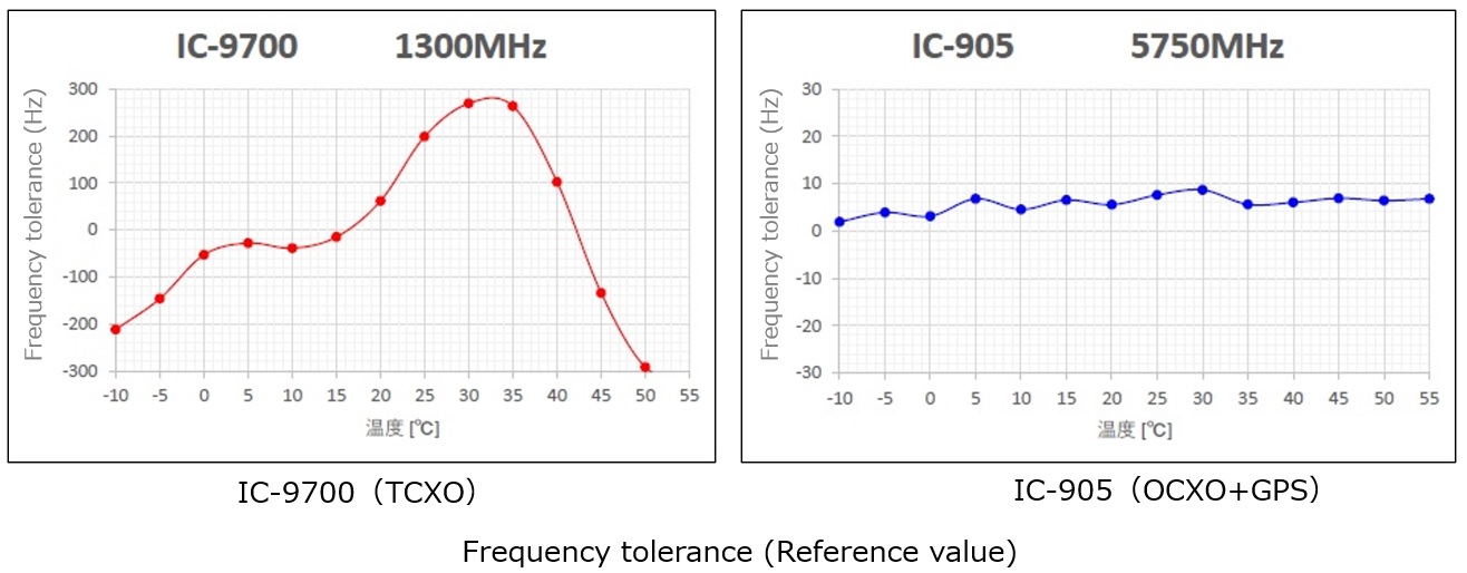
Even if the frequency stability is, for example, 1 ppm, there is a big difference in the absolute amount of frequency shift between the HF band and the UHF or SHF band. 1 ppm at 10 MHz is 10 Hz. 10 Hz frequency shift in CW operation at 10 MHz may cause a slight difference in reception sound, but it does not make QSOs impossible. Although there are not so many extreme cases of 1ppm frequency accuracy in UHF band radios, for example, 1 ppm would mean a 1200 Hz deviation at 1200 MHz. Even if 0.1 ppm is used, this would be a 120Hz deviation, making QSOs in CW difficult. The higher the frequency, the more important frequency stability becomes. In addition, at 10 GHz, the influence is enormous.
At this year's Icom Fair, the frequency stability of the IC-905 was mentioned in a special seminar and provided some very interesting information. The graph below shows the frequency discrepancy between the company's IC-9700 and the soon-to-be-released IC-905 as a function of temperature difference. Although the graph shows a large difference for temperature changes from -10°C to +50°C, the stability of the IC-9700 is not bad at all. The IC-905's accuracy can only be described as excellent, with only a single-digit frequency deviation at 5750 MHz. This is due to the fact that the internal frequency generation circuit uses the internal OCXO and the GPS signal as the reference frequency.
Information provided by Icom Inc.
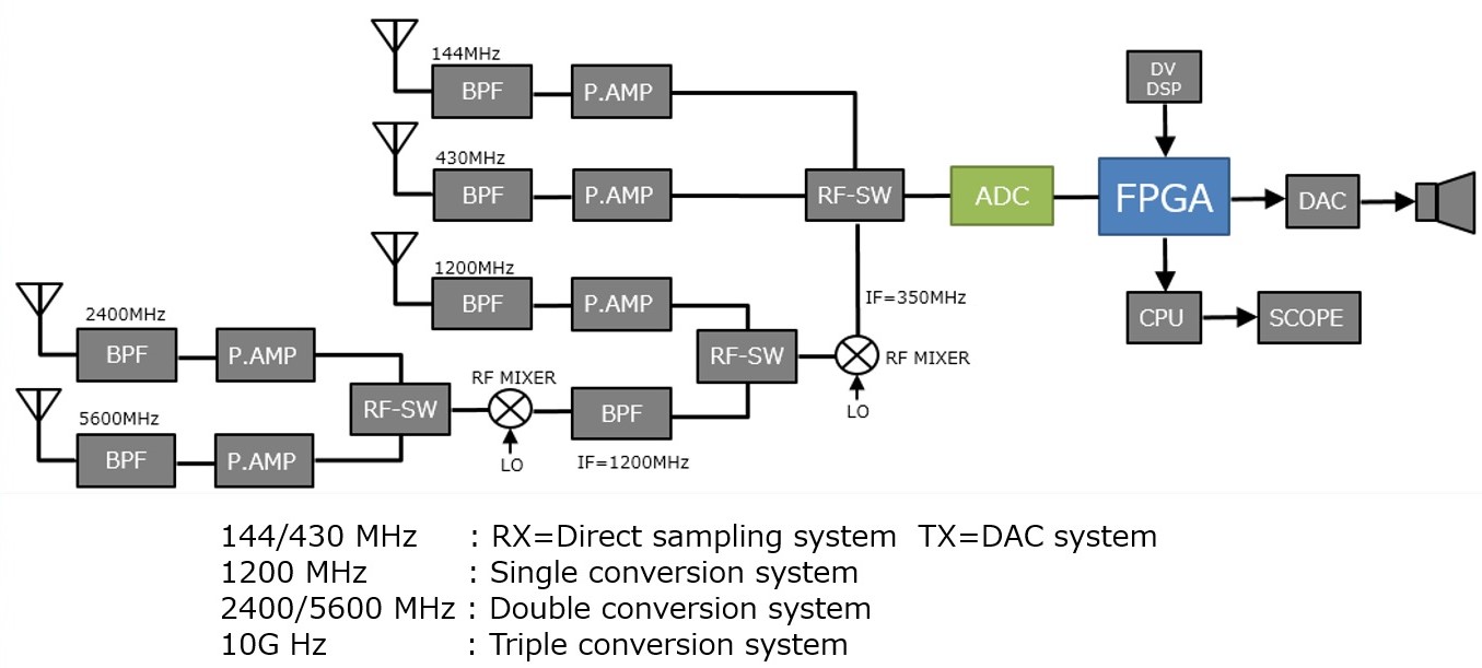
Receiver system configuration
The basic hardware configuration of the transmitter/receiver system is based on the IC-9700, which covers the 144/430/1200 MHz bands. Therefore, the 144/430 MHz bands use the RF direct sampling method for reception and the DAC (Digital-Analog Converter) direct output method for transmission.
Information provided by Icom Inc.
The 1200 MHz band, like the IC-9700, is configured as a single conversion with an IF=350 MHz band through an RF mixer. Signal processing for this IF is the same as for the 144/430 MHz band, with direct sampling for reception and DAC direct output for transmission. For the 2400/5600 MHz band and above, the IF is the 1200 MHz band, utilizing the circuitry of the 1200 MHz band transmitter/receiver system. The circuit blocks of these frequency configurations are housed in a heavy-duty structured RF unit.
The 10 GHz band is operated by connecting an optional CX-10G unit in a separate housing to the 2400 MHz ANT connector on the IC-905. This makes up the circuit for the transverter with an IF of 2400 MHz.
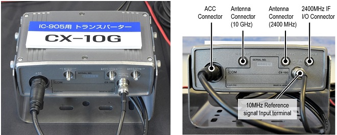
10 GHz transverter for IC-905 (optional)
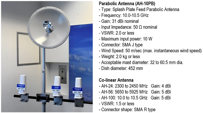
Antennas on display
Next to the IC-905 on display was a parabolic antenna for 10 GHz and collinear antennas for 2400 MHz, 5600 MHz, and 10 GHz. We obtained the specifications for each antenna, but all values are tentative as they are not yet on the market.
FB
Information provided by Icom Inc. and all figures are tentative.