


Technical Trivia by Dr. FB
Is noise actually reduced in twisted pair cables?
Dr. FB
Twisted pair cable and noise suppression
A twisted pair cable consists of two wires twisted together to form a single pair of wires. When you peel off the outer sheath of a LAN cable, you can see four twisted pair cables, as shown in Figure 1, and eight wires in total, as shown in Figure 2. The reason for twisting two wires into a pair is to reduce noise from outside of the cable. Unlike shielded cables, the twisted wires alone reduce noise, and we will confirm this effect through experimentation.
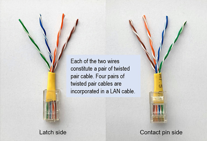
Figure 1. Inside a TIA/EIA568-A LAN cable (4 pairs of 8 wires)
Parallel Cables and Shielded Cables
When we think of noise reduction, we often think of shielded cables used in radio and audio equipment. Shielded cables contain one or more wires and are surrounded by braided metal wires or the like, to form a shielded cable (Figure 2).
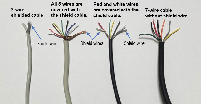
Figure 2. Various types of shielded and unshielded cables
In shielded cables, noise is induced in the braid of the shielded cable and its current flows through the braid to ground, so it does not significantly affect the signal line at the center conductor. On the other hand, a cable that has two parallel wires receives noise as it is, so the noise is superimposed on the input signal, resulting in noise effects. (Figure 3)
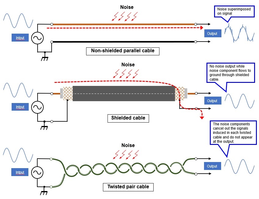
Figure 3. Effects of unshielded and shielded cables on noise
Comparison experiment of the effect of noise on each cable
For the experiment, I used an unshielded parallel cable, a shielded cable, and a twisted pair cable shown in Figure 3. The length of each cable was approximately 1.5 m.
The cables were used as microphone cables for the transceiver. For the experiment, I terminated one end of the cable with a 680 Ω resistor as shown in Figure 4. The resistor should have been 600 Ω but I did not have a 600 Ω resistor on hand, so I used a 680 Ω one. The other end of the cable was input into the microphone jack of the IC-9700. In this way, I could compare and observe the amount of noise picked up by the different types of cables.
If the cable picked up noise from the noise generator, that noise entered the radio through the microphone terminal of the IC-9700, and an RF signal modulated by the noise was output from the antenna terminal. A 50 Ω dummy load was connected to the antenna terminal. The leaked RF signal was received by the IC-705, and the modulated signal was observed on the IC-705's audio monitor screen.

Figure 4. Experiments to investigate the effect of noise on the output signal of parallel cables
Comparison of output waveforms due to noise for each cable
The method shown in Figure 4 was used to force the three types of cables to radiate noise generated by a noise generator from the outside to the signal line. Figure 5 shows the waveforms of the effects of the noise.
Noise can be classified as inductive noise or electrostatic noise, and the noise tested this time was spark noise, such as that generated by the ignition plug of a car engine.
The IC-9700 was connected to a parallel cable, a shielded cable, and a microphone cable made of twisted pair cable, in that order. With each cable connected, I set the IC-9700 to transmit without modulation. I checked the state of the noise picked up by the cable on the receiving side audio monitor with Mic Gain set to 0% with the noise generator not operating, and with Mic Gain set to 50%. (Left and center waveforms in Figure 5)
Next, I turned ON the noise generator and moved each cable closer to the noise source. I observed the noise picked up by the microphone cable on the receiving side audio monitor. (Waveform on the right end of Figure 5)
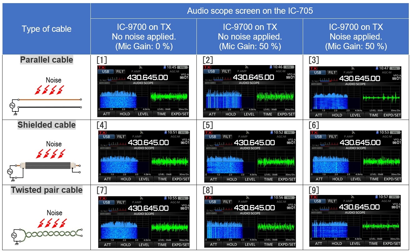
Figure 5. Effects of noise on three types of cables
Experimental result
The parallel cable picked up the spark noise well, and the noise was sent to the receiver in the form of modulated carrier wave through the microphone circuit of the IC-9700 (Figure 5 [3]), which was predictable. (Figure 5 [3])
The shielded cable picked up very little noise. Looking at the waveform in Figures 5 [4], [5], and [6], you can see that there is little difference between each condition.
In twisted pair cables, when noise is radiated into the cable, the waveform in Figure 5 [9] shows that they are not as noisy as parallel cables. Nevertheless, by twisting the paired wires, I expected that the currents induced in both wires would cancel each other out and have an effect similar to that of a shielded cable. This was a little unexpected, and the effect on spark noise was not as strong as I had expected. It may be effective against electrostatic noise other than spark noise, but this is a subject for future homework.
In this experiment, I was only able to visually see the effect on noise, but not quantitatively by raising the numbers. This will also be a future homework assignment.
Spark noise generator but not recommended
In order to generate spark noise, I made the noise generator, as shown in Figure 6. As you can see from the circuit diagram, the (+) and (-) of the DC power supply are shorted by the contacts of a mechanical relay for a very short time. By shorting, a spark is generated between the contacts of the relay.
This may cause the fuse of your power supply to blow, or even activate the protection circuit. In this experiment, I used a 30 A power supply. The time constant of IC1 (NE555) is set so that the short circuit is short enough to prevent the protection circuit from operating. When the generator is operated, you can see a definite spark between the contacts of the relay.
This is not a circuit that I would recommend, so if you build it, please do so at your own risk.
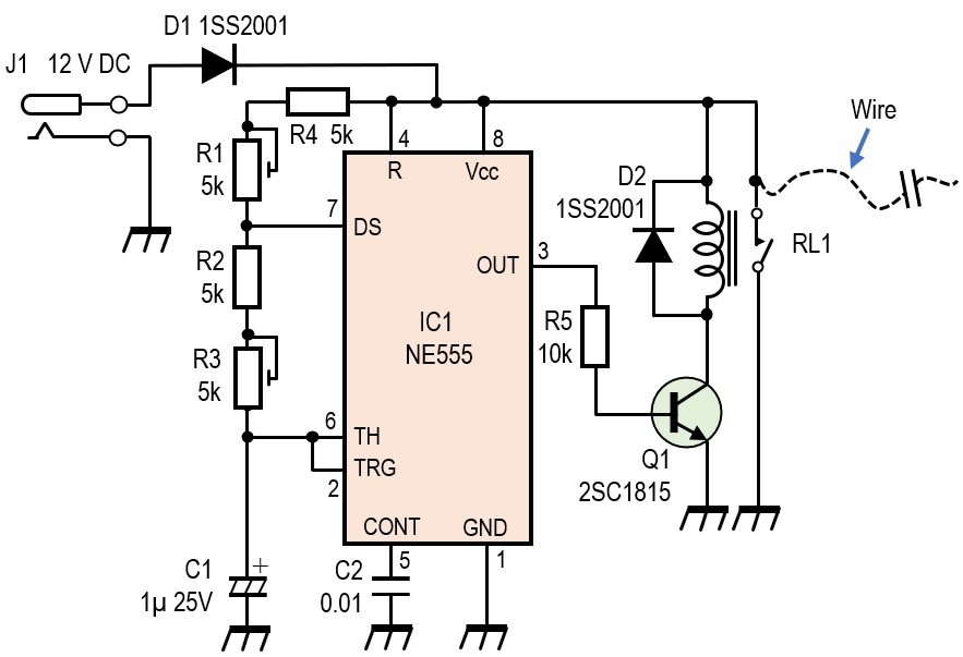
Figure 6. Spark noise generator circuit and operating circuit built into a breadboard
FBDX
Technical Trivia by Dr. FB backnumber
- Generating “Sawtooth Waves” using a D/A conversion circuit and a counter IC
- Examining a D/A converter using a Resistor Ladder
- Electronic firefly and its circuit description
- Controlling the rotation speed of a DC motor
- Description of up-down counter using 74HC192 and 74HC4511 ICs
- Considerations when making a dual voltage power supply for operational amplifiers
- Observing filter characteristics with a white noise generator
- Is noise actually reduced in twisted pair cables?
- Experiments on divider circuits using a 74HC74
- Consideration of using a photocoupler as a voltage-variable resistor
- Distorted waveform spectrum as observed on a tinySA
- Trial making of a QFH antenna
- About the inductance of coils
- Operation of analog switches
- Small digital voltmeter, 2-wire type / 3-wire type. What is the difference?
- Constant current circuit using an Op-Amp
- Coaxial cable loss to UHF and SHF
- 2.4 GHz Wireless LAN Antenna
- Let’s use MOSFETS
- 25th Comparator
- The principle of PLL
- Examination of the MLA performance
- About the Fresnel zone of the SHF band
- Level difference under open and load ends of an SSG
- Is “Made in Japan” alive? (UHF adapter again)
- Possibility experiment of passive repeater with the Back-to-Back antenna
- Why you should make SWR measurements just below the antenna!
- How reliable is the L-type BNC?
- Is the Bird 43 accurate enough?
- Does a wire dipole antenna need a balun?
- Why we don’t use a silicon diode in a crystal radio?
- How to light the 7-segment LED
- Measurement of Antenna Performance on Handheld Transceivers (Part 3)
- Measurement of Antenna SWR on Handheld transceivers (Part 2)
- Measurement of Antenna SWR on Handheld transceivers(Part 1)
- An SWR meter
- V/UHF 3-Band Antenna Dismantling Note