


FB LABO
DIY 50MHz pocket dipole antenna. Portability and Performance!
Hello everyone. Between now and end of July is a period to catch sporadic E propagation for DX contacts. I am writing this article to introduce a home-made version of a compact and portable antenna; a pocket dipole antenna for 50MHz, which is excellent for hiking and field operation.
Components and materials to prepare.
| PVC T-tube VP13 adaptor | 1 each |
| PL-259 connector (for 5D2V coaxial cable) | 2 each |
| SO-239 socket (round base type) | 3 each |
| 1.4-meter telescopic whip antenna with an SMA joint | 2 each |
| 2-Hole Wideband Ferrite Core | 1 each |
| Insulated wire | Approximately 0.5 meters |
| Coaxial cable | Suitable length |
| 2-part epoxy resin adhesive | Suitable amount |
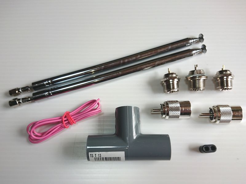
Components that make up the antenna
1. Making the whip antenna element
Now, let me start with how to make the whip element.
I got a 1.4 meter (4.6 feet) telescopic whip antenna from a booth at a JARL event in the countryside of Japan. The market price for the same item is about JPY1,000 (US$9.0) each. Although a 1.5 meter (4.9 feet) one was preferable, it has become a harder item to find these days, but a 1.4 meter one is long enough for the task. In fact, I later found that even 1.4 meter was longer than what is required.
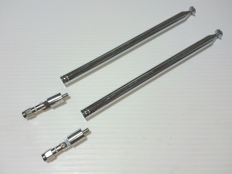
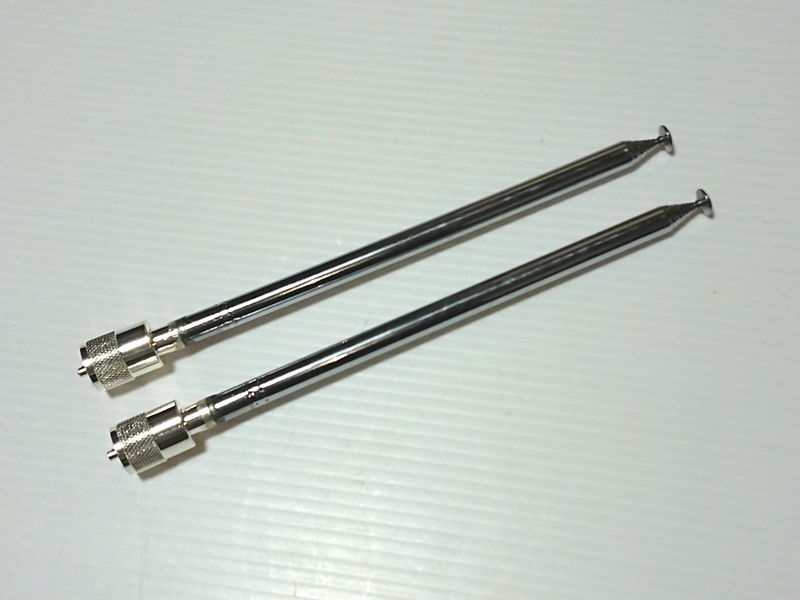
This whip type antenna is composed of 3 sections: the telescopic element section, a short rod section and an SMA connector section. For this project, all of the section parts are used except the SMA connector. A Phillips screwdriver was used to separate the short rod and the SMA connector.
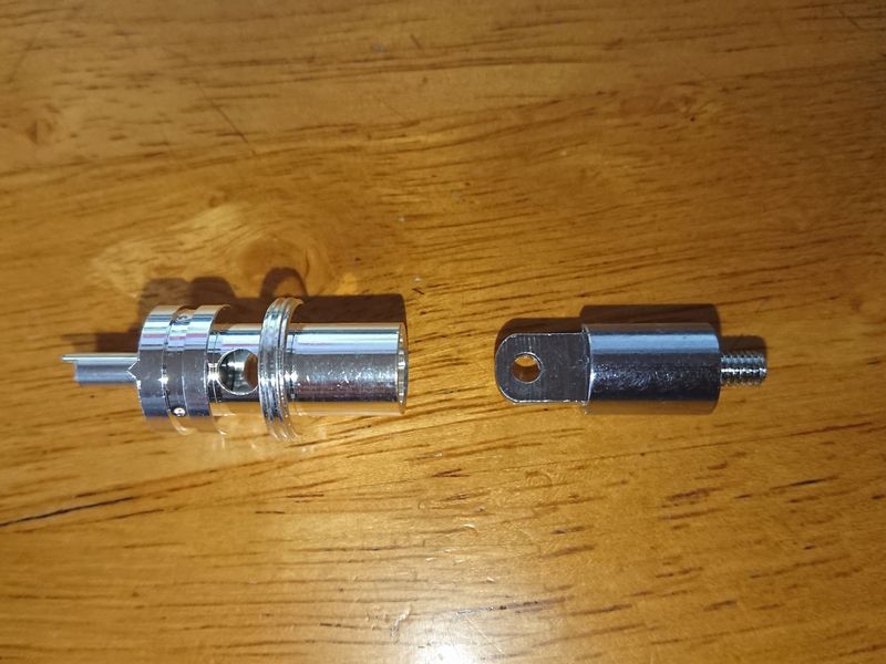
The plate with a screw hole in the middle is part of the short rod which to be inserted to the center of the PL-259 connector.
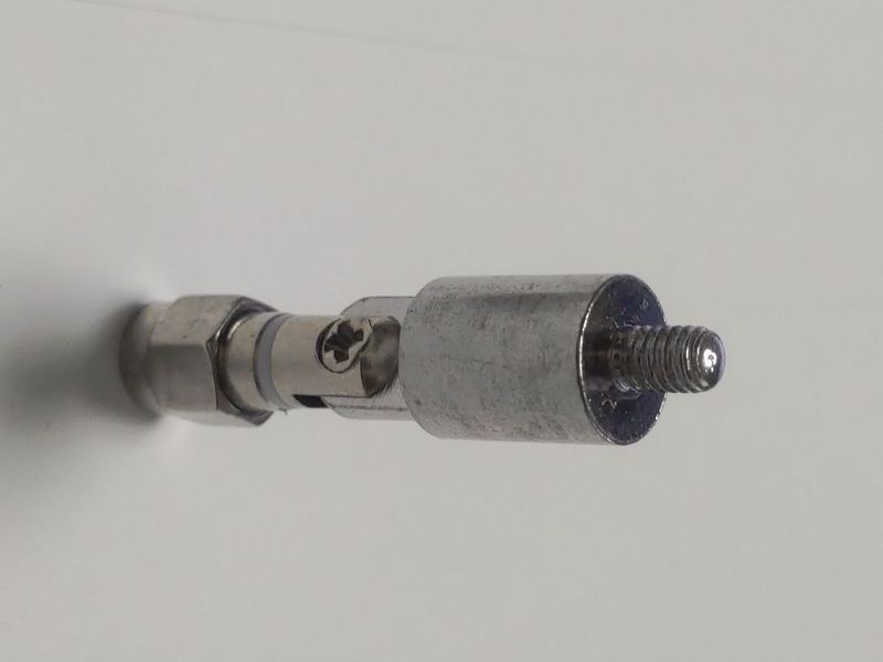
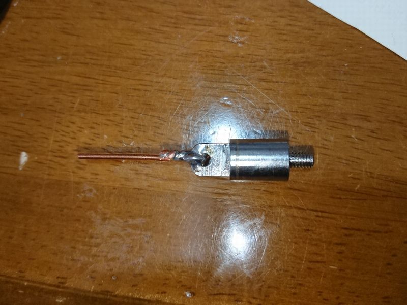
After separating the short rod from the SMA connector, insert a short piece of bare coaxial cable center conductor wire through the hole on the plate of the rod and solder it to the rod, as shown below. Then, insert the wire through the center pin of the PL-259 connector.
Also, glue the rod and connector together using 2-part epoxy resin adhesive. To ensure the strength of connection, I added an extra adhesive circle around the connecting junction. Beware that too much adhesive applied could cause the loss of flexibility of the external contact for the PL-259 connector. Complete the construction by soldering the center conductor wire to the center of the PL-259 connector and cut off any excess wire.
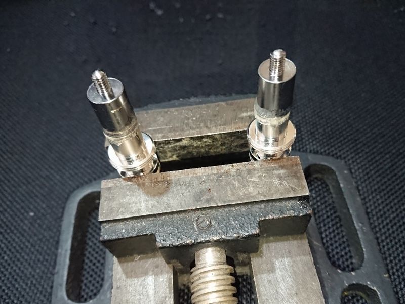
The short rod and the PL-259 connector are glued together using epoxy resin adhesive, and the whip is then connected to the PL-259 connector through the center pin screw. Do not connect these whips directly to a transceiver! Both the hot and cold sides of the PL-259 are connected together, and so operating, especially transmitting, with it directly connected will damage the transceiver.
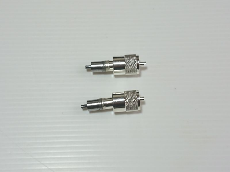
Once the adhesive has completely dried, screw the connector into the 1.4 meter whip.
The elements are complete.
2. Producing a PVC power supplier
This process involves heating up the PVC, which requires extra attention to prevent injury.
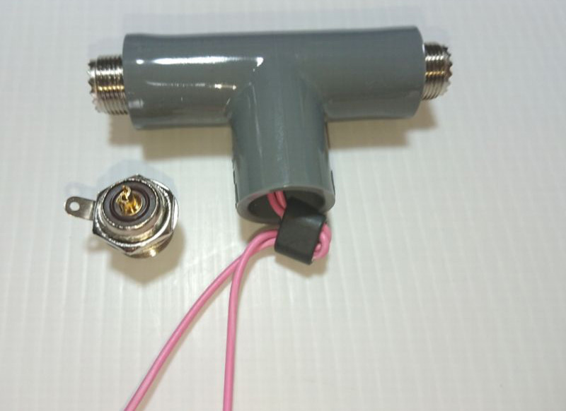
Attaching a 15 to 18 cm (6 to 7 inches) long piece of insulated wire to the center pin of each SO-239 that will go into the ends the T-tube.
The SO-239 hex nut must be tightened up to the center plate of the connector.
Thread both leads of insulated wire through the PVC T-tube. The edges of the hex nuts, however, hit the edges of the pipe opening, so you must heat up the PVC to soften it and enable you to insert the connector inside the opening.
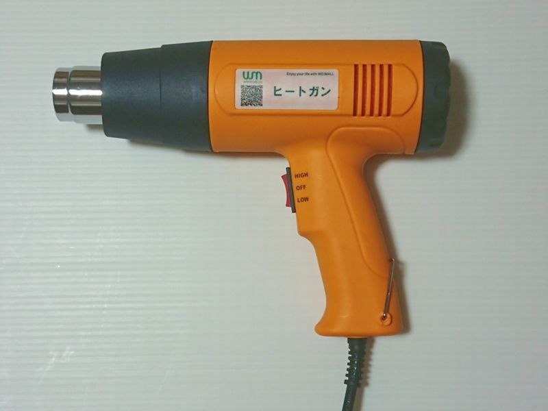
Initially, I heated up the PVC pipe using a gas cassette camp stove, but it burned the PVC quite easily and was dangerous. Therefore, I purchased a heat gun, as shown the photo above, instead. It is certainly safer than using a stove, but since it still requires a high temperature to soften the plastic pipe, you must do this step very carefully, and be sure to wear gloves.
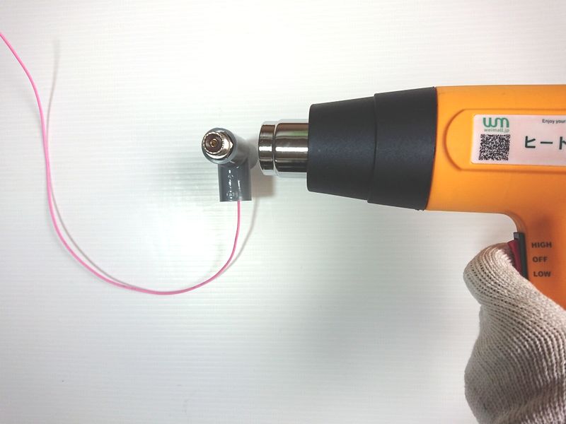
Before heating, the edges of the hex nut are in the way so it cannot fit into the T-tube. The PVC must be heated up to soften it so the nut can be pushed into the tube and positioned straight. Setting the heat gun on HIGH generates 1800 W, which is too hot, so it is better to set the switch on LOW and slowly heat up the pipe. It takes a little time to soften the plastic to the point you can insert the SO-239 into the tube. Be sure to insert the connector into the PVC opening and adjust it to the corrected position, before the plastic cools down. This ensures that the SO-239 is securely and properly mounted inside the PVC tube.
Once both SO-239 connectors are successfully inserted, insert the leads from the T junction of the tube through the holes in the 2-hole ferrite core, to make a simple balun. The 2-Hole Wideband Ferrite Core that I used for this project was obtained from a junk shop in Nipponbashi, Osaka. It does not serve as a perfectly balanced balun, but its main role is to cut off common mode currents. Decide yourself whether it works better to add this type of core in your own antenna. Another option is to use ferrite beads on your coax cable instead, for the same purpose.
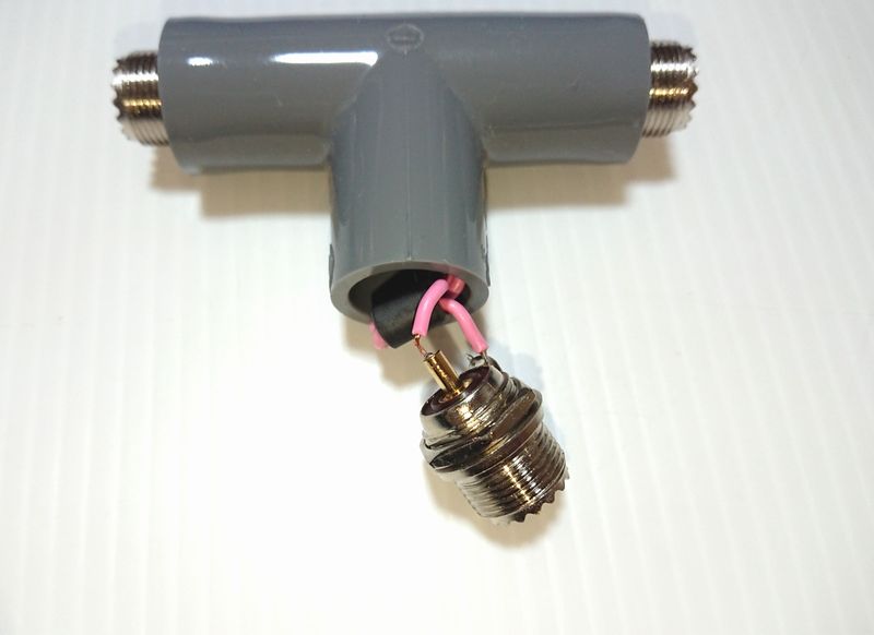
After passing the leads through the ferrite core, measure and cut them to the length needed to connect one lead to the center pin, and the other lead to the ground side of the SO-239. After soldering, heat up the PVC using the heat gun, then push the core and the SO-239 inside the PVC pipe and secure the connector using the same technique used before.
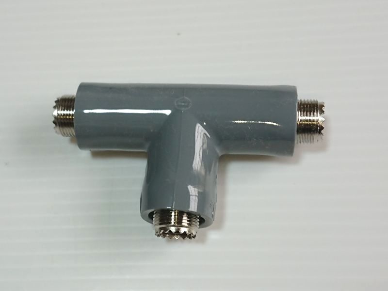
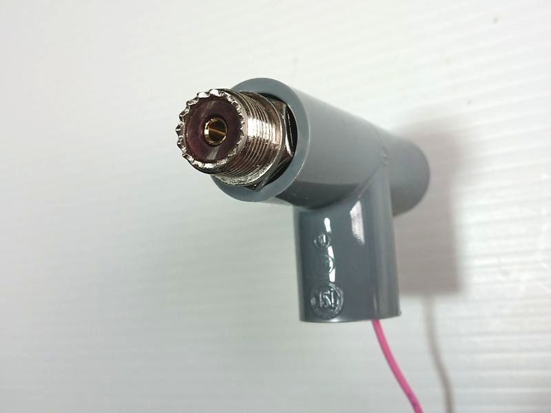
This is the completed PVC center connector.
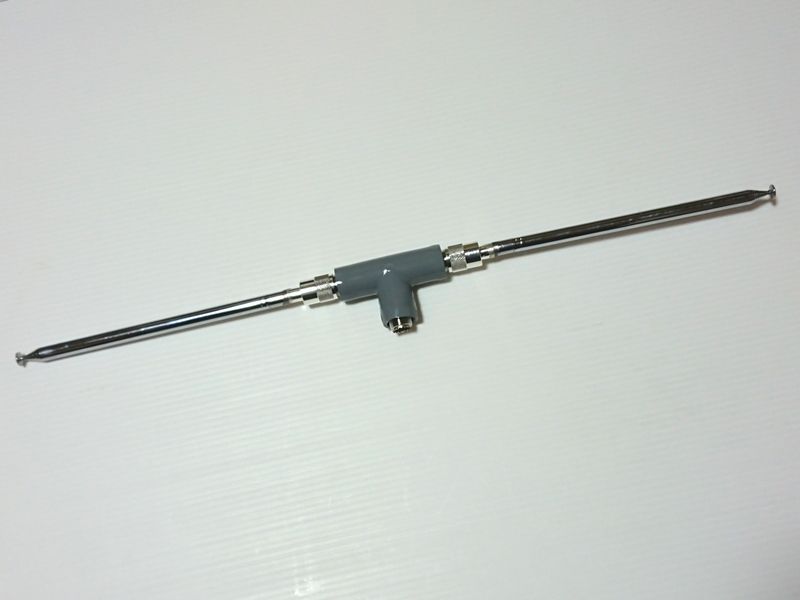
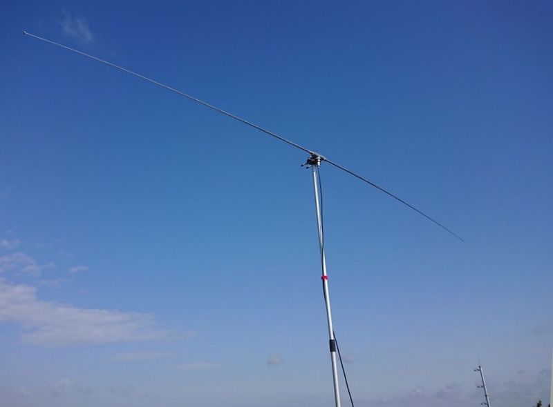
Finished antenna with the telescopic whips attached.
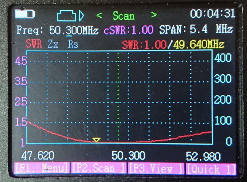
3. Measurements
Using an antenna analyzer to measure the SWR gave me a lot of information about the tuning status. I thought the 1.4 meter was too short, but once I extended the whips, the wide band SWR curve was displayed, as shown below. With such an excellent feature, I could see that the SWR of the frequencies above and below 50.300 MHz does not change that much. Such a wide frequency range provides plenty of operating range to be used under the same tuning conditions. Even when operating around 53MHz, the SWR stays under 1.5:1 without any problem. If I shorten the whip, the SWR at higher frequencies can be adjusted down.
4. Test operation
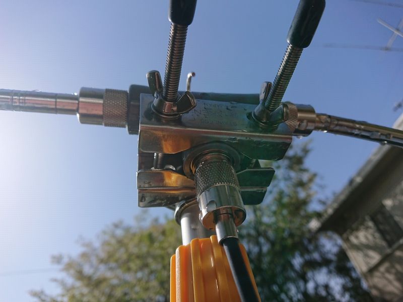
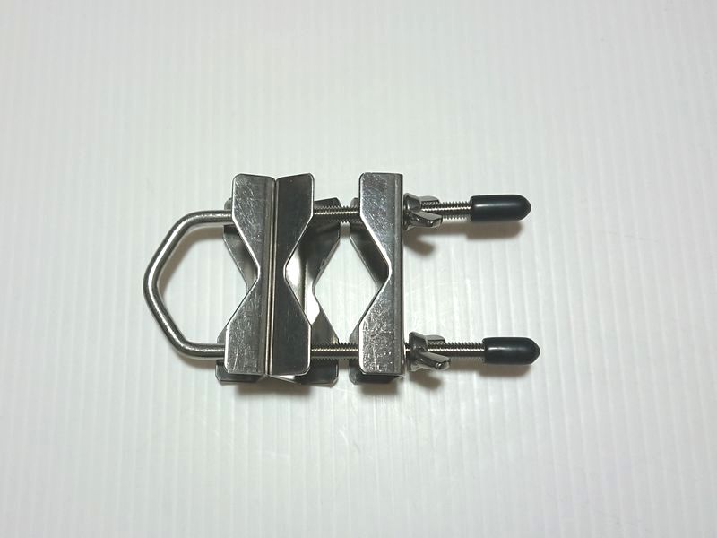
The UB-353 sized 35 clamps attach the VP13 PVC T-tube onto the pole. There are supplied hex nuts, but since I assemble the antenna after I reach the operating location, butterfly nuts are used instead.
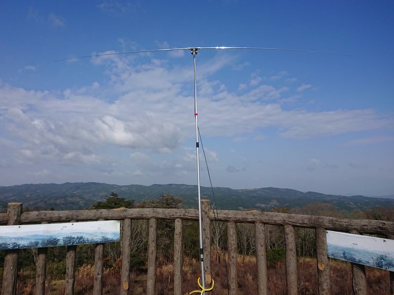
The expandable pole at an altitude of 600 meters (2000 feet), mounted on a summit observation deck in Nara prefecture (JA3 area).
On this day, unlike the usual warmer weather after the cherry blossom season, strong winds resulted in hardly anyone on the observation deck, which gave me a lot of free space to operate. However, the wind was so strong that the notebook I placed on table was constantly blown off, and the expandable pole could not be fully extended. These were not good conditions to operate for long hours. On top of that, sporadic E conditions, unfortunately, did not occur either. However, I was able to contact stations in call sign areas JA2, JA3 and JA4 directly with only 10 W output, and I received “59” reports from each station.
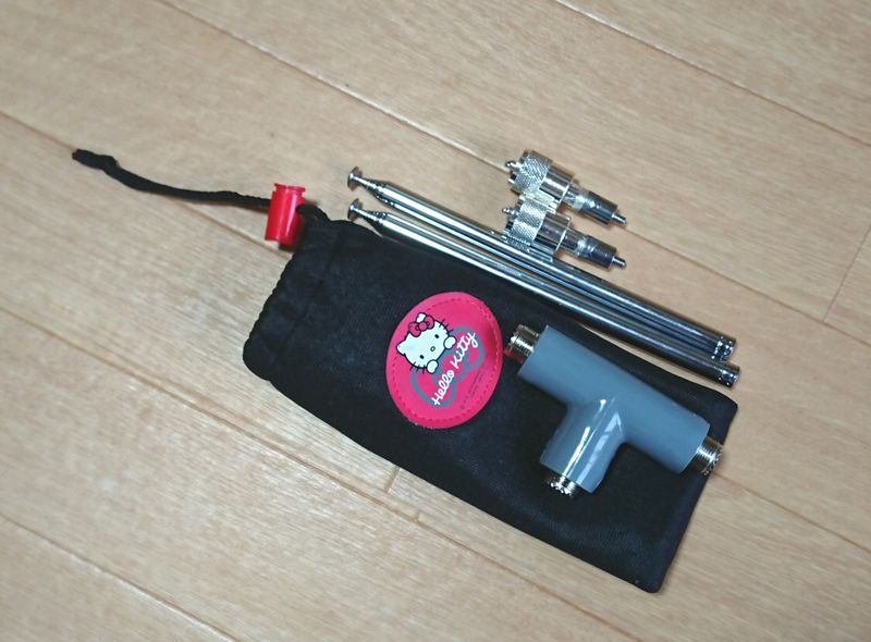
Packing the whole antenna set in a low-price pouch makes it easy to carry around.
So far, this home-made portable antenna has been with me to locations even veteran amateur radio operators have difficulty going to, and places that a large antenna hardly ever goes.
FB LABO backnumber