


FB LABO
Can the HFJ-350M multi-band whip be used to build a V-dipole?
Hello, everyone. I'm going to explore how to expand the fun by modifying a commercial multiband whip antenna. I'm going to try my hand at a two-pronged approach!
1.Encounter with the COMET HFJ-350M
The HFJ-350M multi-band whip antenna was released by COMET Corporation in August 2019. At the time, I wanted to use the IC-703 for easy mobile HF operation at places I stopped by for work or leisure, and I thought this antenna would be just right for that kind of use, so I bought it. I need to adjust it for each band, but with this one antenna, I can operate in 10 bands from 1.9MHz to 50MHz (I bought the optional coil for 1.9MHz later). I was able to operate on the band that was in the best condition at the time. I was very happy to have gotten something so good.
This time, I looked to a new direction by converting a common commercial multi-band whip antenna to discover new ways to use it.
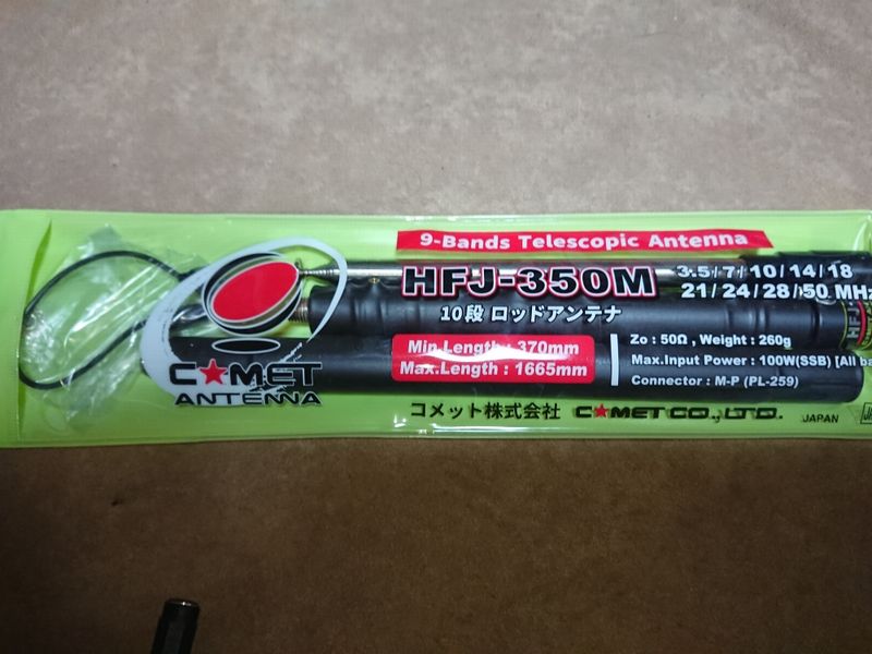
COMET HFJ-350M
In my case, most of the mobile operation with this antenna is done in the CW or RTTY mode. On the HF band, SSB mode is a bit difficult to operate because of the bottom loading system. Of course, it's not impossible to use it, and even in crowded the 7MHz SSB band, I've succeeded in QSO with the IC-705's 10W output (although I don't know the other station’s antenna). However, in order to do this, you need to consider the installation location, radial grounding, and ground conditions, and adjust accordingly. I sometimes found it troublesome when I couldn't get good results.
The easiest way is to install it on the car (not while driving). However, because the door of my car is not well grounded to the body, it took a lot of time and effort to adjust it, and so I mainly used a magnetic ground sheet that I made myself.
After a while, this antenna was left in the car, and I wanted to have the same antenna to use when traveling on foot. At that time, I happened to have some extra points for web shopping, so I ordered another one without thinking deeply. This means that two antennas of HFJ-350M were ready to use.
The new antenna I received was improved that the maximum output power of the 3.5MHz band was changed to 100W, and band indications are displayed for the band change tap. I put a sticker on the tap part of the old one with the band and the rod length.
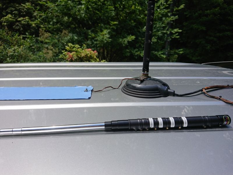
Operating with a home-made magnet sheet
2. How to use the other antenna
This is the second antenna that I bought on the spur of the moment, but of course it is new, clean, and shiny. It was a waste of time to use it, so I kept it, and more than half a year has passed without using it.
One day when I was driving around with only one of them, I was a little frustrated because I had a hard time adjusting it. That's when it occurred to me "If I'm having trouble with the radial, why don't I just use the other one I have left over for the radial?” That’s right let's use two of them to make a dipole. Since I was not using it now anyway, I decided to give it a try.
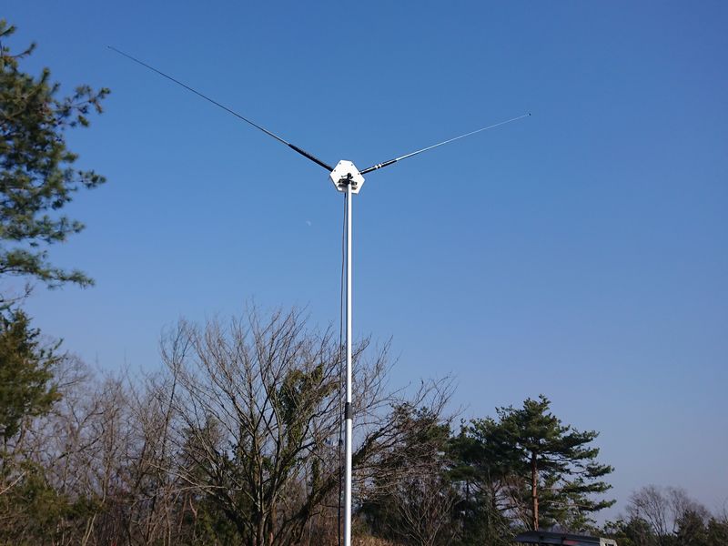
The way I mounted and used the antenna
3. Preparing all necessary materials
I purchased all the materials to be used at a home center store.
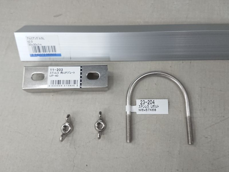
Materials needed to make a dipole antenna
| Resin chopping board 270mm × 170mm × 10mm | Aluminum L angle 30mm×30mm×1000mmL |
| Stainless L square plate UP-40 | Stainless U bolt M6×57mm×68mm |
| Stainless butterfly bolt M6, 2 each | M5 20mm Phillips screw, nut, washer, 6 each |
| SO-239 connector, 3 each | 2-Hole Wideband Ferrite Core, 2 each |
| Coaxial cable 1.5D-2V 30cm | Heat shrink tube, a suitable length |
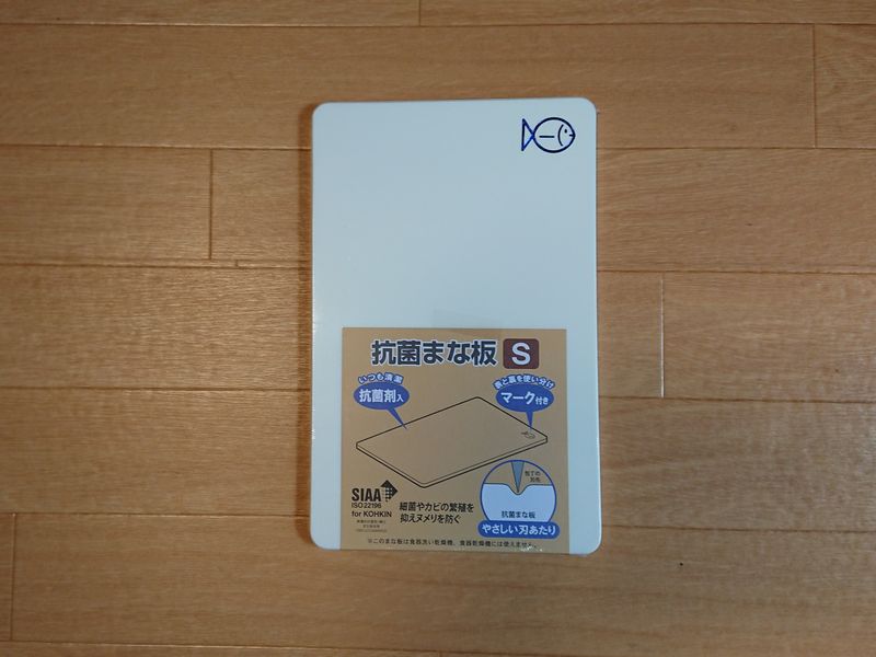
A thick chopping board is high cost, you should use thinner one.
I purchased above materials from the local DIY store.
The chopping board cost about 500yen, but the price goes up one order of magnitude for a thicker, larger one. Look for a store that carries smaller ones. Aluminum angle material is much easier to process than steel, so aluminum is a good choice. You don't need more than 300mm, the size shown above is 1000mm is because they only sell int in 1000mm lengths. We used stainless steel parts, so the price was a little high. If you don't want to install it permanently, or not use it on rainy days, you can buy regular parts at a lower price.
【DIY column】
In the HFJ-350M instruction manual, the length of the rods is described, but the tuning frequency changes considerably, depending on how far the rods are extended. For example, you can adjust the frequency by stretching the rod from the narrow end to the long end. The best point was 21.196MHz.
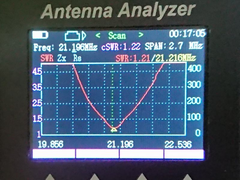
Now, when the rod is fully extended, pull back the thin end and adjust it to the same length as before. In other words, make the rod element the thickest possible and make it the same length. The following are the results of the measurements.
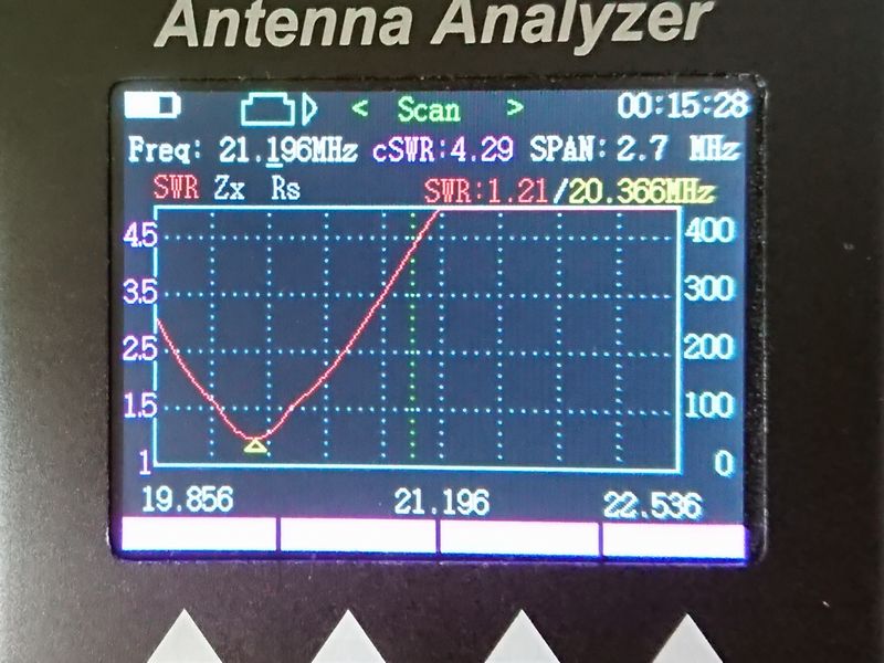
As you can see, even with the same rod length, the best point is 20.366MH, which is over 800kHz lower. The thickness of the element affects the characteristics of the antenna a lot.
4. Making a plate for the dipole whips
The first thing to do is to cut the aluminum angle material into two 100mm lengths and one 65mm length, and drill 16mm holes to attach SO-239 connectors. I used a rechargeable hand drill with a step drill blade to drill the holes. After that, drill two holes for 5mm screws. This was the most difficult part of the work.
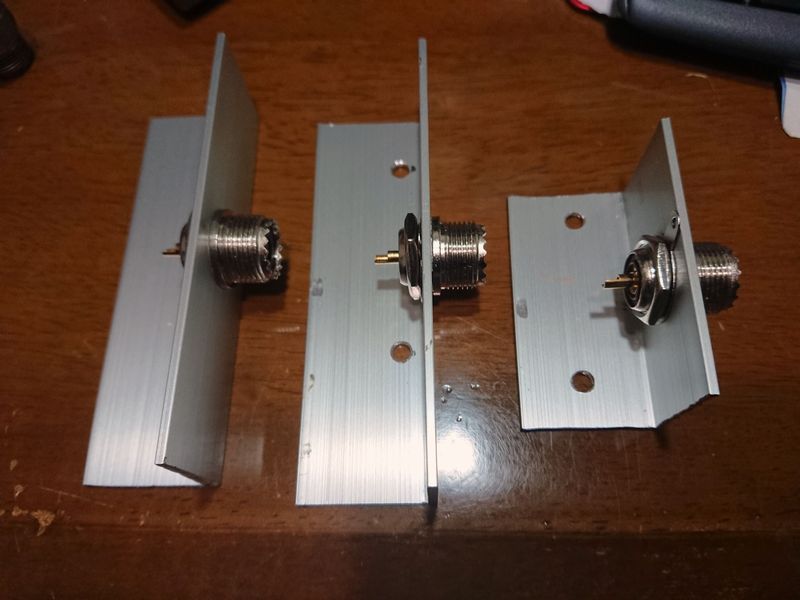
The 100mm angle was a little too long.
Next, I processed the chopping board. First of all, cut the longitudinal direction to 165 mm, and cut the ears diagonally so that the V-angle is roughly 120 degrees. Make sure that the L-shaped angle you made earlier will fit well. You can use a 100-yen metal saw for this cutting work, and it doesn't require much effort.
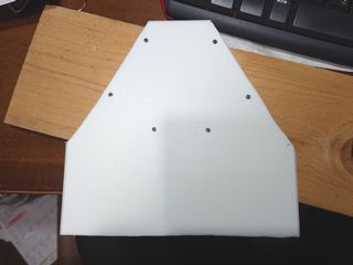
I was able to drill the screw holes easily with a cheap rechargeable drill. After this, I also drilled the holes for the U-bolts to be used for attaching the bottom part to a pole.
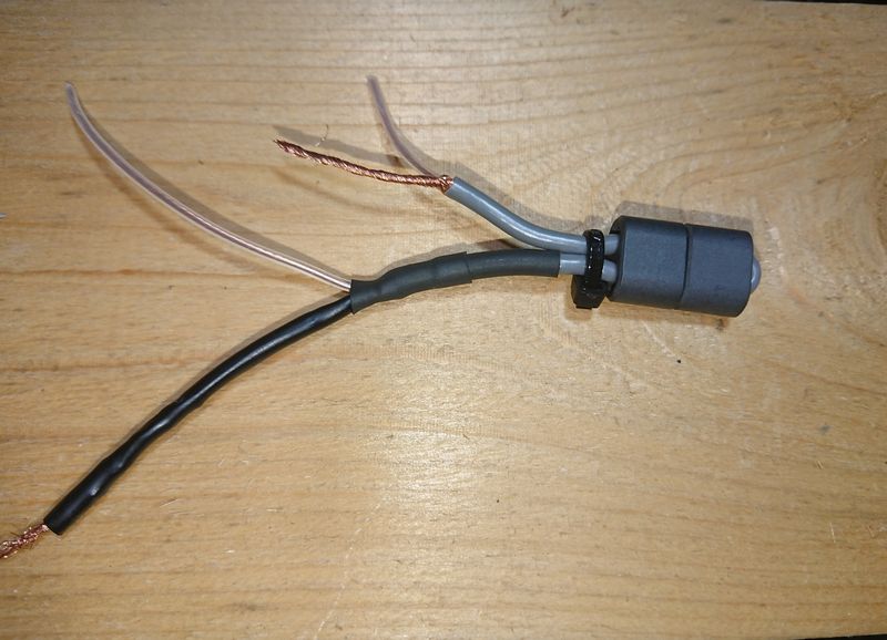
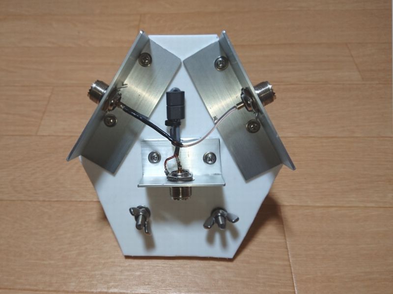
A simple balun using 2-hole wideband ferrite cores.
In terms of wiring, it's just a matter of distributing the center conductor and shield of the coax from the rig to the right and left antenna elements. Of course, you can also use a commercially available balun for this part. If you have an extra balun on hand, you can use it in a creative way. In that case, the 65mm angle will not be necessary. As shown in the photo, the balun passes the 1.5D-2V coaxial cable through two cores and exposes the part necessary for connection. Since I don't plan to support this part, I use heat shrink tubing to provide the necessary strength and insulation to support the weight of the core.
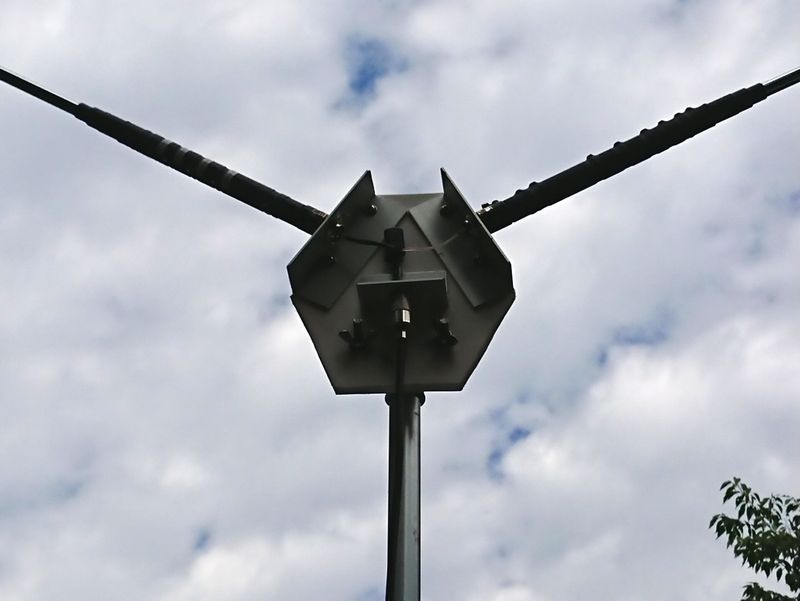
Once the main components are in place, I attach them to the chopping board.
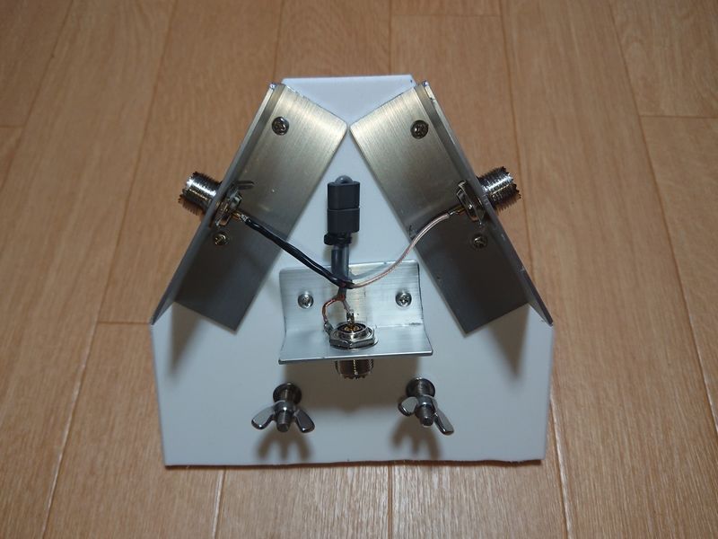
It looks nice and mechanical.
U-bolts and square plates are screwed to the bottom of the plate with wingnut screws to attach it to a pole.
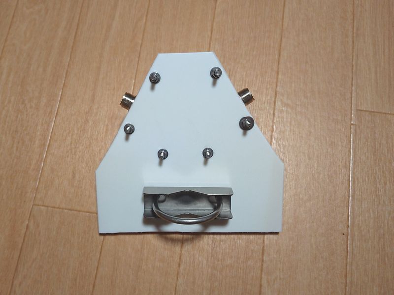
The appearance of the whole plate is similar to a robot
Now that it's done, let's try to use it.
5. Test operation
The wind was blowing very strong on this day.
On this day, the weather was fine, but the wind was very strong, so I set the two antennas to the 7MHz length shown in the instruction manual, as if I were using them in a normal base. Then it tuned in to a very low frequency. It seems that the coax cable was also acting like an element. I used an antenna analyzer to adjust the 6m telescopic pole by extending and retracting it several times. This was quite a tedious task.
When the pole is extended in strong winds, the winds cause the pole to flex a lot. This was partly because the pole I was using was thin, but also because the shape of the plastic board was like a kite, so it seemed to catch the wind. I made the pole half the height and tried to send out a signal. In this case, I was only able to reduce the SWR to about 1.5 on 7MHz. The left and right antennas may be interfering with each other. Even so, the condition in Japan was relatively good, so I was able to communicate with several stations in a row.
Later, I cut the straight part at the bottom of the plastic plate diagonally to reduce the wind resistance significantly. The result is also a little better looking.
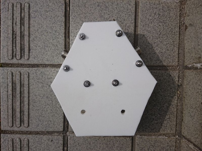
The flashy surface of the plate.
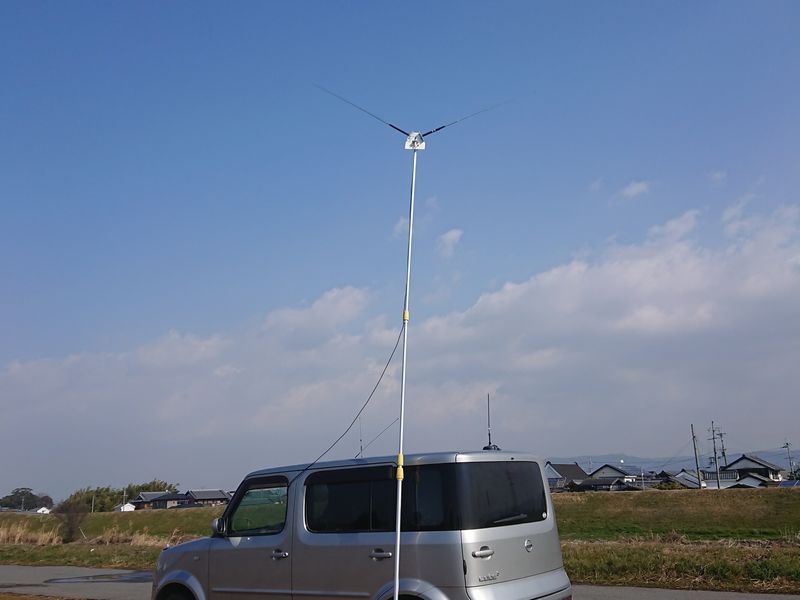
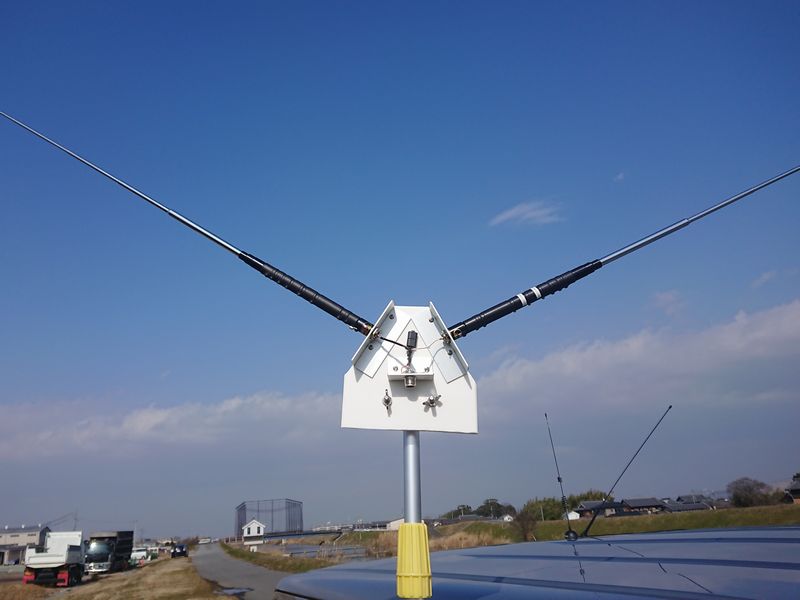
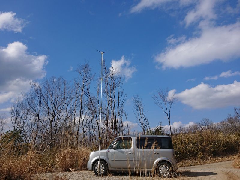
It was a quick test run. The wind was not as strong as last time, but I was able to raise it to 6 meters high without any worries. With this shape, I can raise it up to 6 meters even in winds like the other day.
It is now safe even in a little wind.
6. Summary
After that, I used it several times for portable operation with 10W output. The band change operation was not as smooth as I had hoped, as I had to raise and lower the pole many times to adjust it properly. If I could remember the approximate length of the rods, it would probably be less troublesome, but since it is affected by the surrounding condition where it is installed, it would be difficult to make quick and easy adjustments. There was a case where I couldn't adjust it by any means, and when I checked, I found that I had inserted the left and right taps in the wrong positions.
As I mentioned earlier, the SWR did not drop below about 1.5 at 7MHz, probably because the left and right antennas interfere with each other. After all, I feel that the radiation pattern at low frequencies (3.5MHz and 7MHz band) is not so good either.
On HF, using two antennas of the same antenna does not increase the gain, but at 50MHz, if the other antenna is horizontally polarized, you can get better results than a 1/4 lambda vertical whip antenna by polarity matching, and by raising the antenna higher.
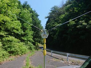
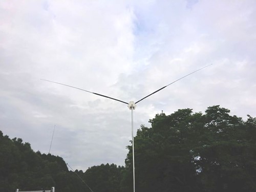
Operating 21MHz in the mountains at an altitude of about 600m.
On the low bands, I felt that it might be better to use it as a single whip antenna. At 50MHz, it is horizontally polarized and can be used as a dipole antenna.
The materials required for this modification were available at DIY store for less than 2,000 yen, but I had to buy two antennas that cost less than 10,000 yen each, so I had to spend about 20,000 yen in total.
The advantage of this system is that it does not require grounding in the HF bands, so it may be worth a try if you do not want to modify your car body but want to go out for mobile operation, or if you cannot get a good grounding due to space limitations. However, there are some quirks as mentioned above, so you will need to take them into consideration.
Add a 1.8MHz optional coil
After the deadline of this paper, I got two coils, HFJ-L1.8/1.9, which are sold separately, and I used them in DP format. This is a report in the form of an addendum.
All coils installed (standard, 3.5MHz, 1.8MHz)
When I added the standard coil, the 3.5MHz coils, and the new coil, each side was almost 2m long, and I was a little worried about the strength of the cutting board feeding part, but it seemed to work somehow. One of the coils I had for 3.5MHz had a power rating of 75W, so I changed it to a 100W one.
Although the season is already summer and it is a difficult time for this band, I tried to operate it at night in Yamazoe Village, Yamabe County, Nara Prefecture (JCG24009). I tried to call the station that had sent out CQ, but there was no response no matter how many times I called. Then I had sent CQ several times. After a while, I got a call from a station in Hyogo Prefecture. After that, I was able to communicate with two stations in Mie and Aichi prefectures, so I had total of 3 QSOs. I felt that I could enjoy this band after autumn when the condition in Japan becomes better.
I didn't expect such a compact antenna to be practical in 1.8MHz band. I was impressed.
FB LABO backnumber