


Radio Geek
Making sequential turn signals

While driving, a car in front of me turns ON its right signal. It is a sequential turn signal that lights up in a flowing manner. It looks cool. I made such a sequential turn signal with general-purpose parts and would like to introduce it to you.

Figure 1. Car equipped with sequential turning signal (Click to play the video.)
Let's make a sequential turn signal
Sequential turn signals equipped on cars are probably controlled by a microprocessor. This time, I will make a turn signal that can be made with general-purpose parts without learning microprocessor programming.
In the "Radio Geek" section, I introduced "Simple Electric Field Strength Meter with LED Display" three times in the February and March 2024 issues. This time, the fabrication of a sequential turn signal is based on the circuits and ideas used in those articles.
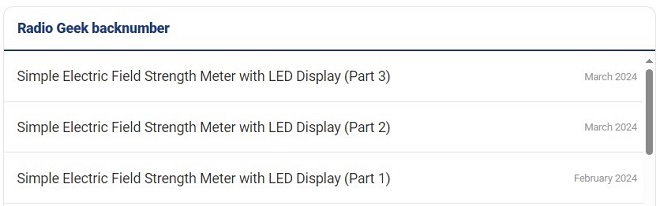
Figure 2. Back issues of "Radio Geek" (Click to select an article.)
The overall circuit configuration is shown in the block diagram in Figure 3. The circuit that is the basis of this sequential turn signal is the rightmost LED Driver in the block diagram. It is a circuit that changes the number of LEDs that light up according to the magnitude of the input voltage. In order to use the function of the LM3914 used here, three circuits are placed in front of it, a D/A conversion circuit, a 4-bit counter, and a clock signal generator. A brief explanation of each block is given below.
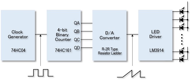
Figure 3. Block diagram of sequential turn signal.
Clock signal generator
A clock signal is needed to generate the sawtooth wave. Figure 4 shows the clock signal generation circuit. It is a simple one using two common inverters. A potentiometer (VR1) is added to allow the oscillation frequency of the clock to be varied. By varying it, the speed at which the sequential turn signals flow can be changed. With this circuit, the oscillation frequency was about 4.6 Hz at the minimum value of VR1 and about 490 Hz at the maximum value.
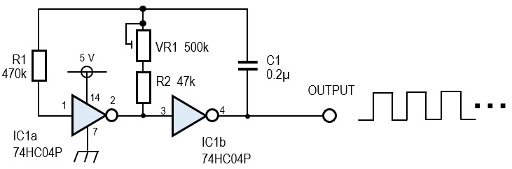
Figure 4 . Clock signal generator uising 2 inverters
4-bit binary counter circuit
One way to generate sawtooth waves is to use a 4-bit binary counter and a D/A conversion circuit.The 74HC161 is used for the counter. When the clock signal shown in Figure 4 is input to CK (pin 2), 4-bit signals such as 0001, 0010, and 0011 are output sequentially at the QA to QD OUTPUT pins, according to the number of clock signal inputs. The term 4 bits means the maximum value is 1111. When it advances to 1111, it repeats, starting from 0000 and going to 1111.
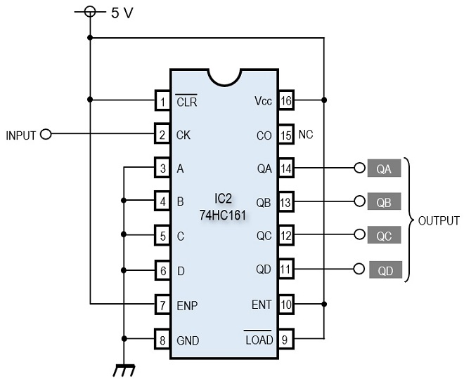
Figure 5. 4-bit binary counter
Digital-to-Analog conversion circuit
When the 4-bit outputs (QA to QD) are input to the D/A conversion circuit shown in Figure 6, a sawtooth wave signal is output from the OUTPUT terminals. It is a strange but natural phenomenon. It is a very well thought-out circuit.
A circuit composed of these resistors is called a "Resistor Ladder." It is used for digital-to-analog conversion. In particular, the resistor ladder shown in Figure 6 is called an R-2R type resistor ladder because it is composed of a 1:2 ratio value that is 5 kΩ and 10 kΩ. Since the ratio is 1:2, a combination of 1 kΩ and 2 kΩ is also acceptable.
By inputting the 0000 to 1111 digital signals output from the QA to QD pins to this resistor ladder, a sawtooth wave signal is output at the OUTPUT pin. Here, we can know that the digital signal is converted to an analog signal of amplitude. Generally, a sawtooth wave signal is a signal in which the voltage gradually rises linearly from a minimum level to a maximum level, drops to 0, then gradually rises again from the minimum level to a maximum level at the next instant, and repeats itself. Here in this version, the minimum level of the sawtooth wave is the GND level (0 V) and the maximum level is 5 V.
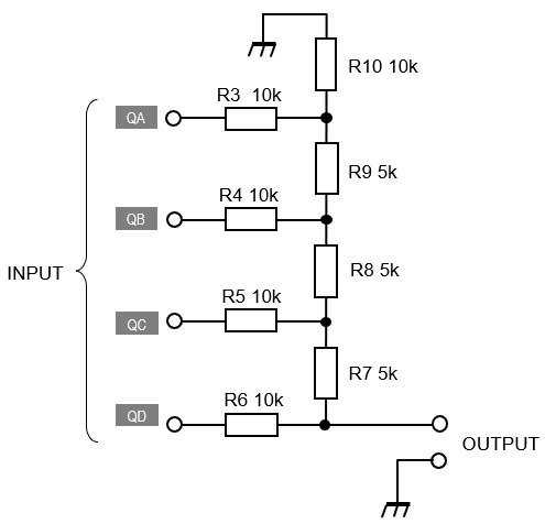
Figure 6. R-2R type resistor ladder performing D/A conversion circuit
LED Driver
The LM3914 is known as a level meter IC. It is an IC that has a function to light up a number of LEDs according to the voltage input to pin 5. For example, if the voltage input to pin 5 ranges from 0 to 5 V, none of the LEDs will light up at 0 V, but at one half of the maximum voltage (2.5 V), five LEDs from DS1 to DS5 will light up, and at the maximum voltage of 5 V, all LEDs from DS1 to DS10 will light up. By inputting this voltage change from 0 to 5 V continuously and repeatedly, the LEDs from DS1 to DS10 will light up continuously and in a flowing manner.
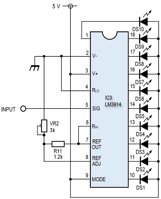
Figure 7. LED Driver
Full Circuit Diagram of the sequential turn signals
Figure 8 combines the circuits described in Figures 4 through 7, each divided into four blocks. It is difficult to fabricate all the blocks at once, but it is easy to fabricate the circuit by dividing it into blocks. It is also possible to check the operation of each block.
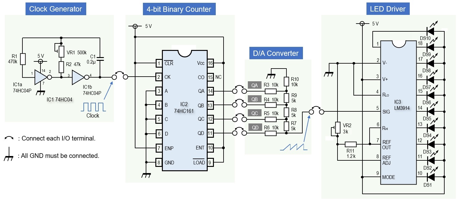
Figure 8. Full circuit diagram of sequential turn signals
Adjustments
After checking the wiring of each block, apply 5 V. If the lighting speed of the LEDs changes by turning VR1, there is no problem. The number of LEDs to be lit changes by turning VR2.If VR1 and VR2 are functioning properly, the sequential turn signal is complete. For detailed adjustment and how to obtain the value of VR2, please refer to the "Simple Electric Field Strength Meter with LED Display (Part 1)."
In the unlikely event that operation is defective, check each block as follows. First is the clock oscillation circuit. If you have an oscilloscope or a frequency counter, connect it to pin 4 of IC1 to check if the clock signal is being output. You can also check the variable oscillation frequency by adjusting VR1. If you do not have a measurement device, you can check the change in oscillation frequency by connecting an LED to pin 4 as shown in Figure 9. If the blinking of this LED changes with the VR1 adjustment, the circuit is operating normally.
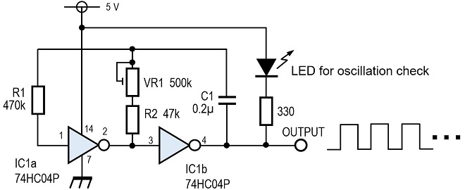
Figure 9. How to check clock signal oscillation
If the lighting does not flow smoothly, you should also check the output terminal of the D/A conversion circuit. If you connect an oscilloscope, you can see at a glance whether a sawtooth wave signal is being output from the OUTPUT terminal of the D/A conversion circuit, but if not, use the same combination of LED and 330 Ω resistor used to check the clock oscillation circuit. This can be confirmed by connecting between the OUTPUT terminal of the D/A conversion circuit and GND. If there is a change in the brightness of the LED, you can see that the sawtooth wave is being output normally.
Summary
By applying 5 V to the completed board, you can see flashing lights on the board equivalent to the sequential turn signals of a car driving on the street.
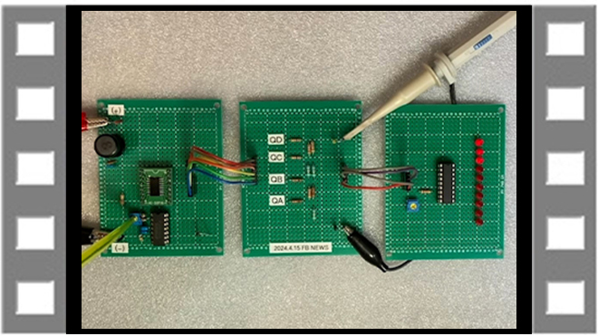
Figure 10. Experiment of the sequential turn signal (Click to play the video.)
The fablication is now complete. Readers are encouraged to think of their own uses for the completed sequential indicator.
CU
Radio Geek backnumber
- Making a 10-second IC Recorder for copying super-fast CW
- Making sequential turn signals
- Simple Electric Field Strength Meter with LED Display (Part 3)
- Simple Electric Field Strength Meter with LED Display (Part 2)
- Simple Electric Field Strength Meter with LED Display (Part 1)
- Again, building a simple inductance meter (Part 2)
- Again, building a simple inductance meter (Part 1)
- Building a simple inductance meter (Part 2)
- Building a simple inductance meter (Part 1)
- Project No.5 Upgrading the counter to 4-digits
- Project No.4 Making a push-up counter
- Project No.3 Making an Up/Down counter (Part 3)
- Project No.2 Making an Up/Down counter (Part 2)
- Project No.1 Making an Up/Down counter (Part 1)