


Radio Geek
Simple Electric Field Strength Meter with LED Display (Part 2)
In the previous issue, I confirmed that the LED Level meter shown on the right side of Figure 1 lights up 10 LEDs sequentially as the input voltage changes using the LM3914. In this issue, I will examine the Detector and the DC Amp that makes the DC voltage to drive the LEDs using the detected signal.
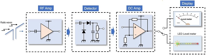
Figure 1. Block diagram of the simple electric field strength meter with LED display
Detection circuit and DC amplification circuit
The field strength meter to be built this time will be built using signals in the 144 MHz band. The 430 MHz band may be easier to experiment with because the antenna is smaller, but the 1N60 diode used for detection cannot keep up with the frequency in the UHF band, so the experiment was conducted at 144 MHz.
In Figure 1, an RF Amp is attached to the front end of the field strength meter, but first, the circuit in Figure 2 is examined to see how much signal can be received without the RF Amp. The circuit has test points TP1 to TP4 to obtain experimental data, but these test points do not relate to the characteristics of the circuit, so there is no need to install them.
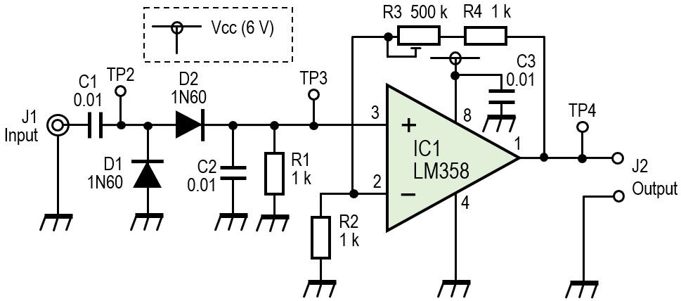
Figure 2. Detection and amplification circuit
Experiment
The experiment is performed with the configuration shown in Figure 3. The experiment measures how well the 144 MHz band signal output from the antenna under test is received at the receiving end.
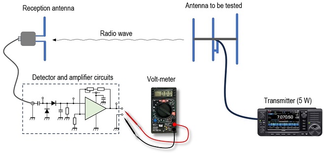
Figure 3. Experiment to measure the level of voltage appearing at the output terminal (J2) with a tester
The antenna to be measured was made by myself for this experiment. The antenna is a 3-element Yagi antenna. The front gain, FB ratio, and directivity of the antenna were not measured. However, when I turned the antenna, I got a strong and weak signal at the reception end. The receiving antenna is a half-wavelength dipole.
For reference, the matching part of the Yagi antenna was a gamma match. The bandwidth of this matching was unexpectedly narrow for approximately 500 kHz, and the SWR varied greatly with changes in the short-bar matching section, making it unsuitable for covering the entire 144 MHz band, from CW to FM.
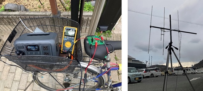
Figure 4. (Left) Equipment packed in a basket on a bicycle (Right) Self-made antenna to be measured
Distance between antenna vs. voltage level
The receiving antenna and the antenna under test were fixed to a camera tripod. As the distance between the antennas was gradually increased, the voltage at each point was measured with a voltmeter. The results are shown in Figure 5. The grey device in the basket of the bicycle is a portable power station unit.
In the previous issue, I explained that this field strength meter is designed to operate on a 6 V battery for outdoor use. I also explained that the maximum input voltage of the LM3914 should be set to 4.2 V, 1.8 V lower than the supply voltage. The maximum value of the output voltage is determined by adjusting R3 in the circuit shown in Figure 2. This is why the voltage at J2 appears to be saturated at 4.2 V when the distance between the antennas is between 1 and 3 m.
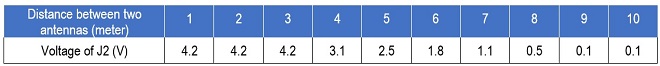
Figure 5. Relationship between the two-antenna distance and the level of voltage
The experiment was conducted in a wide parking lot. I learned that when a person or a car passes a few meters away, this voltage rises and falls, and the field strength is found to be affected by the surrounding environment.
Discussion
The experimental results show that the detection output voltage also changes as the electric field strength changes. The result in Figure 5 shows that the detection output is almost zero when the distance between the antennas is about 10 meters (about 5 λ) when the transceiver output power is in 5 W operation with the IC-705. So, I increased the amplification of the amplifier circuit composed of LM358 by increasing the feedback resistor value of R3. In order to obtain higher sensitivity, I experimented with incorporating an RF Amp in the front stage, which was my original plan, but this only increased the overall noise level and did not give good results.
In the next issue, I will experiment with connecting an LM3914 to the output of the circuit shown in Figure 2 to light an LED.
CU
Radio Geek backnumber
- Making a 10-second IC Recorder for copying super-fast CW
- Making sequential turn signals
- Simple Electric Field Strength Meter with LED Display (Part 3)
- Simple Electric Field Strength Meter with LED Display (Part 2)
- Simple Electric Field Strength Meter with LED Display (Part 1)
- Again, building a simple inductance meter (Part 2)
- Again, building a simple inductance meter (Part 1)
- Building a simple inductance meter (Part 2)
- Building a simple inductance meter (Part 1)
- Project No.5 Upgrading the counter to 4-digits
- Project No.4 Making a push-up counter
- Project No.3 Making an Up/Down counter (Part 3)
- Project No.2 Making an Up/Down counter (Part 2)
- Project No.1 Making an Up/Down counter (Part 1)