


Radio Geek
Making a 10-second IC Recorder for copying super-fast CW
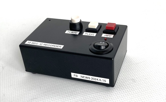
Completed the 10-second IC Recorder
Call sign, can't copy at first!
When listening to the 40 meter band, I sometimes encounter a frequency that has a CW pileup. I want to call on the pileup somehow, but CW transmitting is too fast and I can't copy call signs at first. Therefore, I made a recording and playback device that can record the CW sound and then I can listen to it over and over again. In essence, it is a hand-made version of an IC recorder. A board that can record up to 10 seconds is available at a reasonable price in online vendors, so I made a "10-second IC recorder" using it.
Recording and playback board with ISD1820 nonvolatile memory
The key component used in the IC recorder is a record/playback board with ISD1820 nonvolatile memory installed. (Figure 1) This board is available from online vendors. You can find quite a few vendors.
The nonvolatile memory used in this board is a type of semiconductor memory used to store data. In other words, even if the power is turned off, or the battery is removed after recording, the data is retained in the IC.
This recording and playback board was previously used in the making of the FB News "Making a sound machine." Please browse through it if you have time, as it may be helpful in its usage.
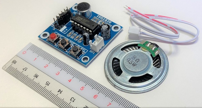
Figure 1. Recording and playback board kit with the ISD1820
Checking the operation of the record/playback board
The recording/playback board does not come with an electrical specification sheet or a flyer showing how to use the board. Therefore, I searched the Internet for "ISD1820" to obtain the board's specifications and information on how to use the I/O pins on the board. You will find a lot of information on websites.
First, check the minimum necessary materials for the build shown below. If you have the following three items, plus a dry-cell battery box, you can immediately check the operation without any test equipment. Note that the voltage supplied to the board is 4.5 V from three 1.5 V dry cell batteries, based on the information that the voltage is 3.3 to 5 V.
1. Recording and playback board
2. Speaker
3. Speaker cable between the board and speaker
■ How to check the operation of the board
(1) Connect a speaker and a battery(4.5 V) to the board.
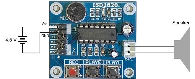
Figure 2. Connection for operation check
(2) Speak into MIC while pushing "REC." LED (D1) lights up during recording.
(3) When recording is complete, release "REC."
(4) Push "PLAYE" to play the recording once.
(5) Push "PLAYL" to play the recording for as long as it is pushed.
(6) When the recorded content is played back, the confirmation is complete.
(7) Remove the battery box and speaker for safety.
Case drilling
Switches and LEDs necessary for recording and playback are already installed on the purchased board, but they will be attached to the case as external components to improve operability. The three switches do not need to be removed, but will be added as new external components. The recording/playback board is equipped with I/O terminals for control by Arduino or other devices, so I used them.
The case for installing the board and batteries is a 100 x 65 x 35 mm resin case for easy processing. On the front panel of the case, I install switches for [REC], [PLAYE], and [PLAYL] as well as a power switch and an indicator (LED) to show the recording/playback status. Holes for speakers are also drilled in the bottom of the case.
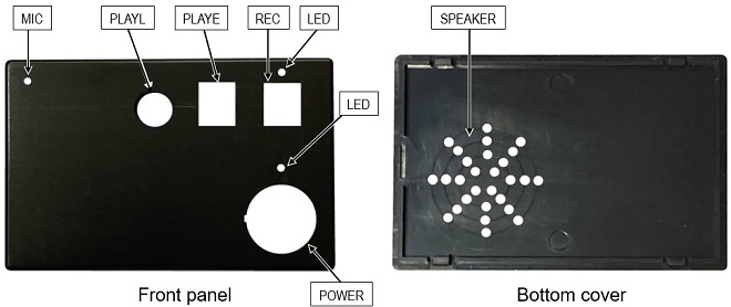
Figure 3. Drilling holes in the case for mounting external components
Connecting the board to external components
Remove the microphone element (MIC) and D1 (LED) from the board. The MIC is to be reused, so remove it carefully to avoid breaking it. D1 is an LED that looks like a chip resistor mounted on the board. Use a soldering iron with as sharp a tip as much as possible to remove the LED without breaking the surrounding components. This LED will not be reused. Therefore, it does not matter if it is broken. Solder wire to the anode and cathode terminals of the board from which D1 was removed, respectively, as shown in Figure 4. These lead-wires are used to connect to an external LED.
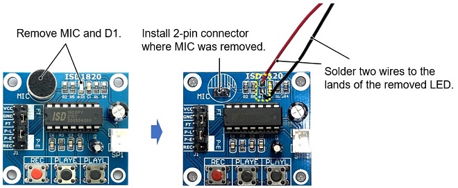
Figure 4. Remove the microphone element and LED from the board
Connect external switches for [REC], [PLAYE], and [PLAYL] to the pins of the J1 connector on the board. The speaker and battery box are mounted on the bottom cover of the plastic case. Connect each external component to the recording/playback board through a relay board to avoid complicated wiring. The relay board is newly made.
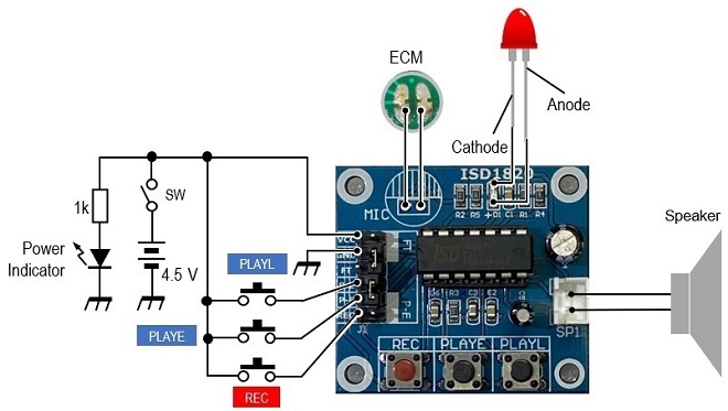
Figure 5. Connection diagram of board and external components
Casing
The record/playback board, relay board, battery case, and speaker are all built into the case.
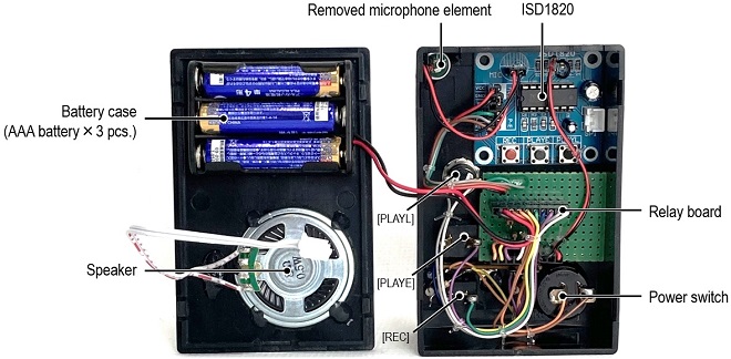
Figure 6. Inside of the completed "10-second IC Recorfer" with each board built into the resin case.
Operation check
Turn ON the power switch of the device. Speak into the MIC while pushing [REC]. The recording LED will light up during recording. When recording is complete, release [REC].
To playback, push [PLAYE] or [PLAYL]. If the recorded sound comes out of the speaker, the device is complete. Now you can practice by pushing [REC] near the radio's speaker when you encounter a pileup.
I used the IC-705's CW memory function to output a super-fast CW on 30 WPM signal from the speaker, and tried recording and playing back that signal with the 10-second IC recorder. The video is stored in the site below for your reference. Figure 7 shows a unit with colorful switches installed, called an external keypad, placed on the front of the IC-705. This unit enables you to externally control of the IC-705's eight built-in memories. The information is described on the IC-705 Instruction Manual. Click here for more information.
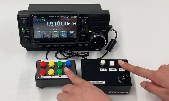
Figure 7. IC Recorder in operation (Click to play the video.)
Supplemental description of the ISD1820 record and playback board
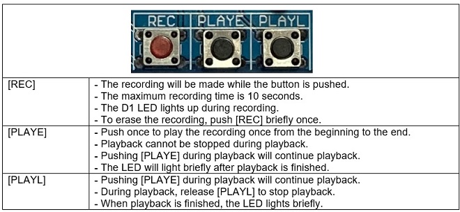
Figure 8. Functions of each switch
CU
Radio Geek backnumber
- Making a 10-second IC Recorder for copying super-fast CW
- Making sequential turn signals
- Simple Electric Field Strength Meter with LED Display (Part 3)
- Simple Electric Field Strength Meter with LED Display (Part 2)
- Simple Electric Field Strength Meter with LED Display (Part 1)
- Again, building a simple inductance meter (Part 2)
- Again, building a simple inductance meter (Part 1)
- Building a simple inductance meter (Part 2)
- Building a simple inductance meter (Part 1)
- Project No.5 Upgrading the counter to 4-digits
- Project No.4 Making a push-up counter
- Project No.3 Making an Up/Down counter (Part 3)
- Project No.2 Making an Up/Down counter (Part 2)
- Project No.1 Making an Up/Down counter (Part 1)