


Short Break
Making a sound machine say “Good morning. Thank you for everything.”
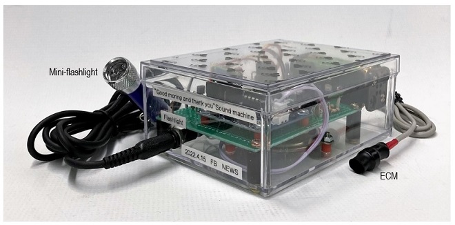
Completed Sound Machine
In Japan, night falls much earlier in mid-April. Even so, it is still dark at 4:30 AM in the morning. But when I go out to pick up a newspaper at this time, it has already been delivered, even on cold and rainy winter days. I can only be grateful to those who deliver it. So, I made a "Thank you for everything" sound machine using a sound module with a record/playback function that I had been saving for a CQ voice device. This sound machine detects the sound of newspapers being dropped into a mailbox, and automatically says, "Good morning. Thank you for everything" with a pre-recorded voice from the speaker, and also turns ON a spotlight in the mailbox.
Although this sound machine does not play a direct role in our daily operation of amateur radio, the circuits used in the device are useful for your electronic projects.
Specifications for the sound machine
Basically, it is a device that allows pre-recorded voices to be heard from a speaker to those who deliver newspapers before dawn.
<Basic specifications>
a) The device operates on dry cell batteries (4 x AAA batteries: 6 V).
b) Energy-saving design that operates only in the dark.
c) The voice to be recorded can be freely rerecorded.
d) Detects a sound when the newspaper is dropped in the mailbox.
e) Pre-recorded sound is emitted from the speaker.
f) Inside of the mailbox illuminated with a mini flashlight.
Circuit configuration
The seven circuits from (1) to (7) shown below are largely combined to produce this device. The overall circuit diagram combining the circuits of each block is shown in Figure 3.
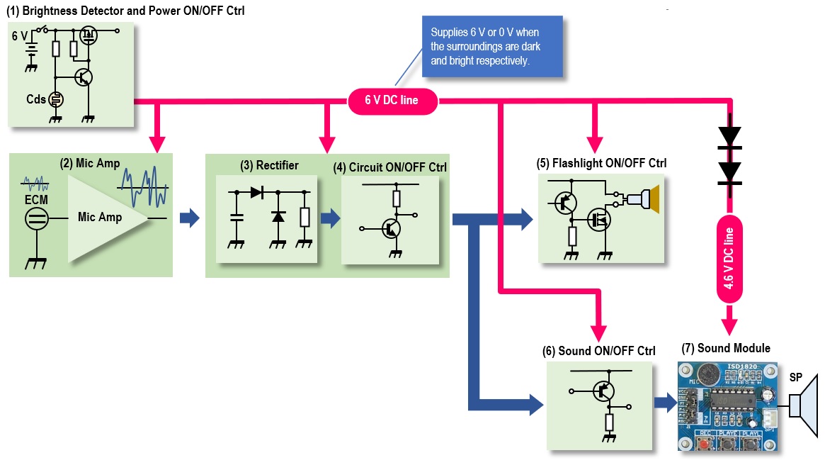
Figure 1. Block diagram of the sound machine
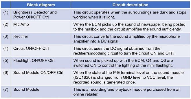
Figure 2. Description of each block
Overall schematic diagram
The overall schematic diagram of the completed sound machine is shown in Figure 3.
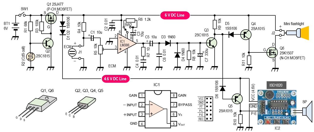
Figure 3. Overall schematic diagram
Description of each block
(1) Brightness detector and power ON/OFF control circuit
This circuit is not necessary if you want all-day operation. This circuit is equipped with CdS cell (R2), which detects ambient brightness and supplies power to each circuit only when the ambient is dark. When the ambient light becomes brighter during the day, the circuit stops operating because the daily life noise increases, and the device may malfunction with the noises or sounds. A CdS which detects the ambient light, is a kind of photoconductive element mainly composed of cadmium sulfide, whose resistance value changes, depending on the amount of light hitting the surface of the component (photosensitive area). The resistance of the CdS is very high (several MΩ) when the ambient are dark and drops to several kΩ when the ambient become brighter. This is used to operate the sound machine in the dark and turn it off when the ambient light becomes bright.
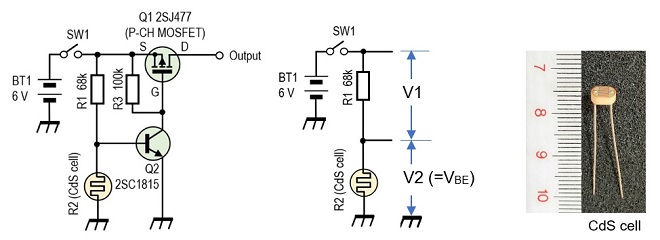
Figure 4. Detector circuit of ambient brightness
Find the resistance of R1. The resistance of the CdS is measured first with a multimeter. The voltage applied to the base of Q2 is obtained by dividing the voltage between R1 and the resistance of the CdS, R2, as shown below.

Here the resistance of the CdS is calculated as 10 kΩ when the ambient light is bright. When Q2 turns ON, VBE = 0.7 V. Since VBE = V2, R1 can be obtained by substituting numerical values into the above equation, as follows.

Based on the above calculation, when the ambient light becomes dark, and the resistance of R2 becomes 10 kΩ or higher, the voltage at the intersection of R1 and R2 becomes 0.7 V and Q2 turns ON.
Q1 is a P-channel MOSFET, and the gate voltage goes to GND level when Q2 turns ON, and Q1 also turns ON, outputting 6 V from its drain. When the ambient light becomes bright enough to illuminate the CdS, its resistance decreases and the base voltage of Q2 falls below 0.7 V, Q2 turns OFF, Q1 also turns OFF, 6 V is cut off, and the circuit operation is stopped.
(2) Microphone amplifier
A condenser microphone (ECM) picks up the sound of newspapers being dropped into a mailbox and converts the sound into a DC signal to control each circuit. It is also interesting to use, for example, a motion sensor instead of sound. I will try again another time.
The ECM is not specifically named on the schematic diagram, but a general-purpose ECM should work without any problem. In this circuit, the voltage is applied through R4. The microphone amplifier uses the familiar LM386 Low-voltage audio power amplifier. The gain of the LM386 can be switched by a component connected to pins 1 and 8. In this device, as shown in Figure 5, the gain can be switched between 50x and 200x as needed.

Figure 5. Microphone amplifier circuit and amplification level switching
(3) Rectification and smoothing circuit
The sound picked up by the ECM is amplified by the LM386, and the amplified AC signal is rectified by D3 to DC. The diode is a 1N60 germanium diode with a low junction voltage to allow rectification of as weak a signal as possible. A silicon diode used for normal switching can also be used, but with slightly lower sensitivity. The 330 µF of C7 acts as a smoothing circuit to convert the rectified diode signal into DC with as little difference in amplitude as possible.
(4) Circuit ON/OFF control circuit
After the sound is picked up by the ECM and the output of IC1 is converted signals from AC to DC with D3, the DC voltage is applied to the base of Q3 to turn Q3 ON.
(5) Mini flashlight ON/OFF control circuit
This circuit can be omitted if the mini flashlight is not needed. When Q3 is turned ON by sound detection, the collector of Q3 goes to GND level, and since Q4 is a PNP transistor, it turns ON as well when the base of Q4 goes to GND through D5. Q6 does not need to be a MOSFET, a bipolar transistor can be substituted.
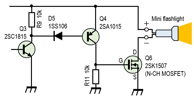
Figure 6. Mini flashlight ON/OFF control circuit
(6) Sound module vocalization ON/OFF circuit
This vocalization control circuit is basically the same as the mini flashlight ON/OFF control circuit shown in Figure 6. When Q3 is turned ON by sound detection, Q5 is turned ON, producing a voltage close to VCC at both ends of R10 inserted between the collector of Q5 and GND. By applying this voltage to the P-E terminal of the sound module, the state of the P-E terminal changes from L to H, and the sound module will vocalize the recorded voice once.
(7) Sound module
The key component is this sound module, which was purchased with the intention of using it to build a CQ machine.
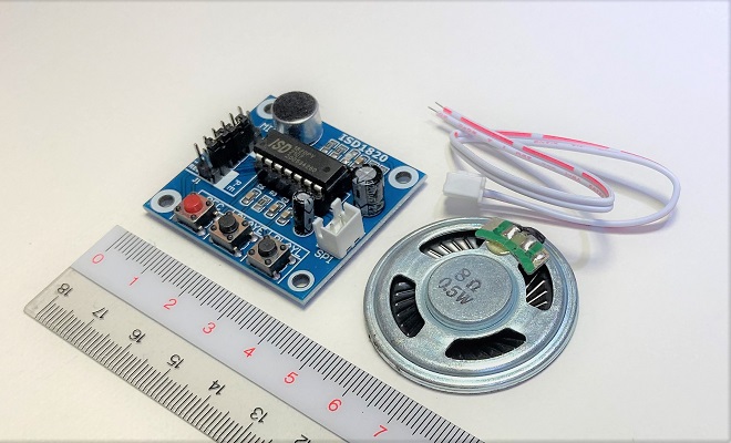
Figure 7. Sound module with recording and playback functions
It is quite costly to try making this module by yourself. It is surprising that one module can be purchased on major mail-order sites for as little as 2 US dollars. The module contains a non-volatile memory IC and a condenser microphone (ECM) for voice recording. It also comes with a speaker, so all you need to do is connect the power supply for 3 to 5 V. The module can record audio for 10 seconds. The module does not come with an instruction manual, but you can search the Internet for ISD1820 which will give you some hits.
The module measures 38 mm x 42.4 mm and weighs 12 g. The function of each button switch on the module is shown below.
[REC] button: While holding down, speak into the ECM to record for up to 10 seconds.
[PLAYE] button: Pushes once to play the recorded sound once.
[PLAYL] button: Plays back the recording for as long as you hold it down.
This module has I/O terminals that can be controlled externally, such as with an Arduino. The pre-recorded sound is played back once by changing the state of the P-E terminal from "L" to "H." This state change is performed by turning Q6 ON and OFF.
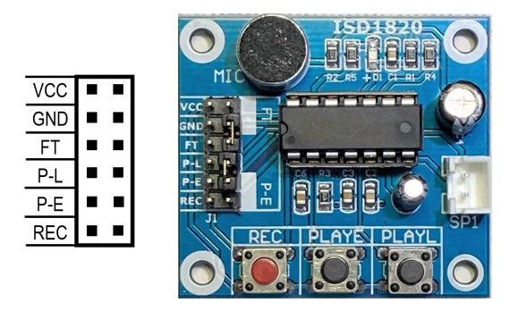
Figure 8. ISD1820 Sound module
Appearance of the sound machine
Since I could not find a suitable case, I installed it into a transparent plastic case that I had on hand. The reason for using the transparent plastic case is because a light sensing CdS cell is installed on the PCB. If a case that does not allow light to pass through is used, some ingenuity is required to install the CdS.
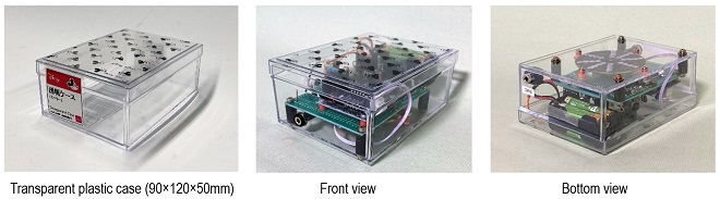
Figure 9. Appearance of the sound machine
Each part name
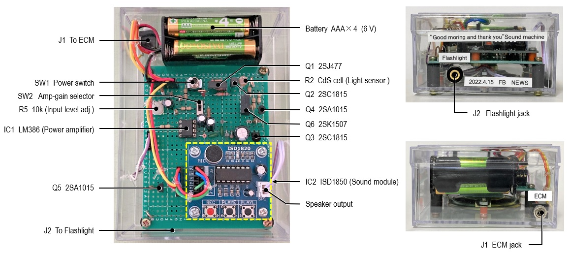
Figure 10. Individual part names
Modifying the external components
The ECM and mini flashlight are externally mounted, and the ECM is covered with thick heat-shrink tube to increase its strength. The mini flashlight was made by modifying a give-away flashlight that I got as a promotional item from Icom at a previous amateur radio exhibition. Both have a 50 cm cable with a 3.5 mm speaker plug installed.
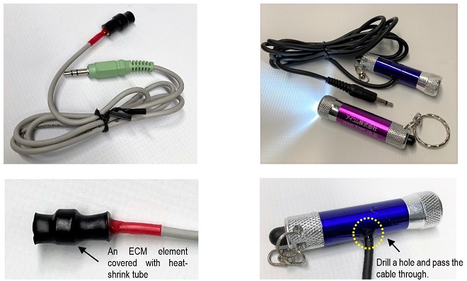
Figure 11. External ECM and modified mini flashlight
Modifying the external components
I mounted the sound machine on the bottom of the mailbox with strong double-sided tape. The ECM and the mini flashlight are mounted inside the mailbox through a gap and with cables running through it. The ECM was mounted with double-sided tape near the mailbox cover so that it would detect the sound when the cover is opened.
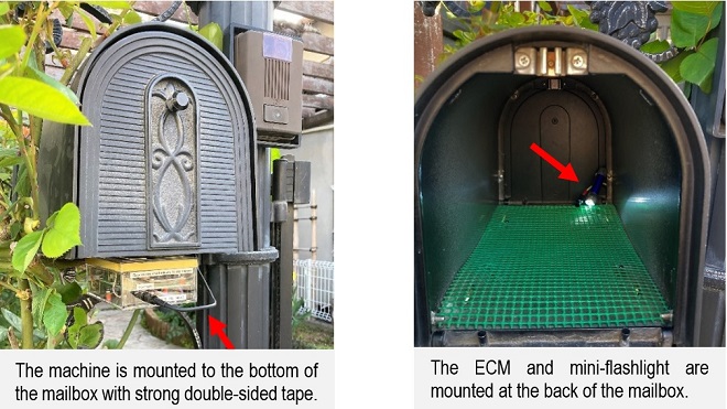
Figure 12. Mounting the sound machine
Adjustment
Adjust R5 so that the device works reliably with a sound when the mailbox cover is opened because the device may work by picking up ambient sounds, even if no one opens the mailbox. If the sensitivity is poor, switch SW2 to GAIN = 200.
After many test runs, the sound machine worked perfectly. When the sound machine runs perfectly, the newspaper delivery people will hear "Good morning and thank you for everything.” when they put the newspaper into the mailbox.
One morning when it was still dark outside, I heard the sound of a newspaper delivery motorcycle. As soon as he stopped in front of our house and put the newspaper in the mailbox, the machine said, "Good morning. Thank you for everything.” I heard the greeting from inside the house. Now, I am wondering what the newspaper delivery person thought about my greeting.
CL
Short Break backnumber
- How many colors do you see when a colored disc is rotated at high speed?
- Making a dual Positive/Negative voltage power supply in a single box, for experiments
- Building of an RF Volt-Ammeter for QRP operation
- White noise generator project
- One day electronics project – Making a simple antenna tuner for QRP operations
- Can the RHM12 portable antenna be matched with a bicycle body on HF?
- Making an “ON AIR” lamp using LM358
- Making a simple anemometer
- Making a sound machine say “Good morning. Thank you for everything.”
- Electronics project for the 10 MHz reference signal generator (2)
- Electronics project for the 10 MHz reference signal generator (1)
- Making a straight type AM radio using a TA7642 IC
- About splitters
- Electronics project for FB NEWS: Making a decoration light string
- Making a Simple Electric Field Strength Meter
- Building a simple QRP power meter
- Building a 20 Amp electronic DC load device using an N-channel MOSFET for the load
- Building an automatic backup power switching unit
- Overvoltage protection device using LM358: Part 2
- Building an Over Voltage Protector: Part 1
- Making a 50 MHz monoband MLA without a variable capacitor
- Making a 50 MHz monoband MLA.
- Let's connect a computer headset to the IC-705
- Building a microphone selector
- Building an audio amplifier using an LM386 IC chip
- An External Keypad for Icom Transceivers
- After all, is the receiver good for Up-conversion?
- Find the gain of the stack antenna
- The mystery of controlling the microphone and PTT with only two wires
- RFID tag