


From Steve's Workbench
Another SOTA antenna, and some thoughts on antenna efficiency
Every portable HF antenna that I have built has had some drawbacks. My first one was a lightweight parallel dipole for 14, 18, and 21 MHz which was very effective, but it needed tall supports and got twisted easily. My “chair-tenna” is a full-sized multi-band vertical groundplane (VGP) that works very well but is tricky to tune and bulky to carry. I have written in FB News about lightweight magloop antennas*1, which are effective but have several parts to assemble and need good support due to wind resistance. And sometimes I use a 16-meter end-fed “random” wire, but it also needs a tall support pole and an antenna tuner.
The antenna I will discuss here is not an original design. Shortened vertical antennas are standard for HF mobile operation and are popular for portable use. My contribution has been to make one that is very light, easy to set up and tune, and can be homebuilt for the price of a few Big Macs. I brought it to Fiji last month, set it up outside my hotel room in my spare time, and made solid QRP contacts into Europe (15000+ kms), Asia, and Oceania. Good propagation and a rare callsign helped, but later testing showed that this antenna really works well. I also learned a lot as I built it, including why antenna efficiency is not well understood.
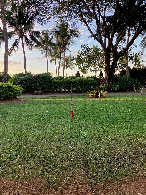
Figure 1. The new vertical antenna in Fiji, May 2024
The Challenge:
Dozens of portable antenna designs can be found online*2 along with calculators for making shortened antennas*3. They range from practical to rather bizarre and most claim to be efficient. Wire antennas like dipoles are popular with SOTA and POTA operators because they are lightweight and effective, but require open space and supports like trees or guyed poles. Vertical antennas need less space, are easier to set up and are usually better for DX. Portable operators change bands very often, so antennas with traps, links, or a tuner are used. A simple and popular vertical antenna is just a wire supported by a pole, used with a short counterpoise and an internal tuner or one like the ICOM AH-705. There are some verticals that use heavy adjustable coils that can fail mechanically, or rigid sections for different bands that are not adjusted easily, or else have parts to assemble that can get lost or forgotten at home. Several commercial antennas use a very short whip with a small, high inductance coil, but these trade efficiency for portability. My ideal SOTA antenna would have only the good features of these designs, and emphasize light weight (I’m not a strong hiker) and efficiency (I only use low power). I think I succeeded, but first let’s look at some antenna theory…..
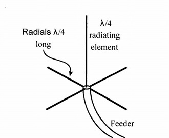
Figure 2. The basic parts of a vertical groundplane antenna

Figure 3. Full-size and handheld SOTA antennas
Why loading coils?
An antenna is a closed circuit connected to an RF power source (the transmitter) through a transmission line, and radiates power into space. It is efficient if all the RF power fed into it is radiated. Because of current and voltage phase relationships, it acts like a capacitance and an inductance in series with its radiation resistance and loss resistance (Figure 4). At resonance the inductive and capacitive reactance cancel, leaving only the resistance that determines the “Q” of the antenna. Long antennas have higher radiation resistance than short ones and radiate better. If an antenna is longer than the resonant length, it has net inductive reactance and can be made resonant by adding capacitance in series, but most portable antennas are shorter than resonant length. The capacitive reactance of a short antenna can be cancelled with a series inductance or loading coil, but the short antenna also has low radiation resistance, which means more power is dissipated in the loss resistance. This is the main reason that shortened antennas have lower efficiency. A loading coil in a vertical antenna can be adjusted to obtain low VSWR, having the advantage of simplicity over other matching devices. It is correctly pointed out that low VSWR does not mean an antenna is efficient, with a dummy load often used as an example, and an L/C circuit that does not radiate at all may have sharp resonance. In resonant circuits (including all antennas), this can indicate high “Q” and relatively low loss resistance.
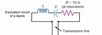
Figure 4. Equivalent circuit of a dipole antenna
Loss Resistance and Efficiency:
Even the best HF antennas are only 50% or 60% efficient because they are made of and surrounded by real materials, but this is only an estimate because there is no way to directly measure radiated power except at microwave frequencies. The earth or a conductive groundplane makes half of a vertical antenna, and antenna efficiency is reduced by wire resistance and by energy that is coupled into the earth. Hams agree that the most important part of a station is the antenna, but disagree intensely about what makes an effective ground. Many who use extensive ground systems with resonant radials or hundreds of meters of buried wire believe that it helps the antenna radiate more power. Old experiments done at low frequencies did show this to be mostly true but the gains were small. Terms like "high efficiency" and "low ground losses" are meaningless without controlled measurements, but power lost to the earth cannot be measured. This gives rise to unprovable claims like, “I can break pileups with 100 watts/I made DXCC in a week/I can work anyone I hear.” But, since I have bragged about QRP DX from Fiji, later on I will defend this with evidence the antenna is really good.
Radials or counterpoises:
Based on my own experience and that of other builders and commercial manufacturers*4 of vertical antennas, an extensive ground radial field or exactly tuned radials are not as important as believed, and in any case are usually not practical for portable use. Many videos show portable operators spreading out long radials for their vertical antennas, but even an authoritative reference*5 says that a few radials as short as 0.1 wavelength can work. I found an online report*6 by a respected experimenter who modeled a 28-MHz VGP with short radials. He found that radial lengths between 0.5 and 3.5 meters resulted in antenna impedance close to 50 ohms when the vertical element was adjusted for resonance. The radial lengths affected gain and bandwidth very little, and results were similar with two, three, or four radials and over a range of elevation angles. I extrapolated his results to lower HF bands by multiplying the range of lengths for 28 MHz by two (for 14 MHz), four (for 7 MHz), and so on. I found that radials between 2 and 2.5 meters long should result in feed impedances from 40 to 80 ohms on all bands, giving a good impedance match without any adjustment. I confirmed this with VSWR measurements on actual test antennas and by later on-air comparisons.
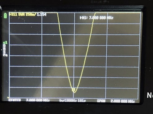
Figure 5. VSWR of coil-loaded vertical on 7 MHz. Narrow resonance indicates high “Q”
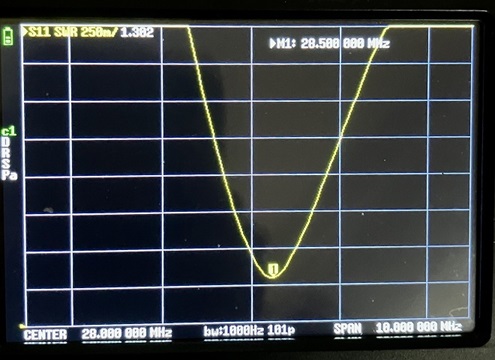
Figure 6. VSWR of shortened vertical on 28 MHz with loading coil bypassed
Building a practical antenna:
I need an efficient antenna because 7 MHz is the most popular HF band for SOTA operation in Japan*7, but daytime propagation from Okinawa to the mainland is usually poor. A full quarter-wavelength vertical is 10 meters tall and not practical for casual portable operation. A very short antenna would be inefficient, but a medium length such as 1/8-wavelength has a radiation pattern and gain close to a full-size VGP*8.
Good quality, lightweight and inexpensive stainless steel whip antennas with extended lengths of 2.5 or 5.7 meters are widely available, and the longer one is over 1/8 wavelength on 7 MHz. The base of a vertical is not the most efficient position for a loading coil, but it is easy to adjust there and allows a telescoping whip to be used as the antenna. I wound a test coil with aluminum wire on an old trap core and found that 13 µH (microhenries) inductance would resonate the longer whip on 7 MHz. With some turns bypassed it could tune the 10 MHz band, and with the whole coil bypassed the antenna could be shortened to tune from 14 MHz to 30 MHz. When fully extended, the short whip needed an additional 12 µH to resonate on 7 MHz.
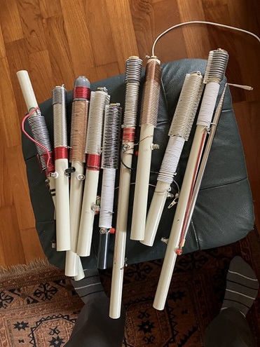
Figure 7. Some of the early prototypes of the loading coil and mounting
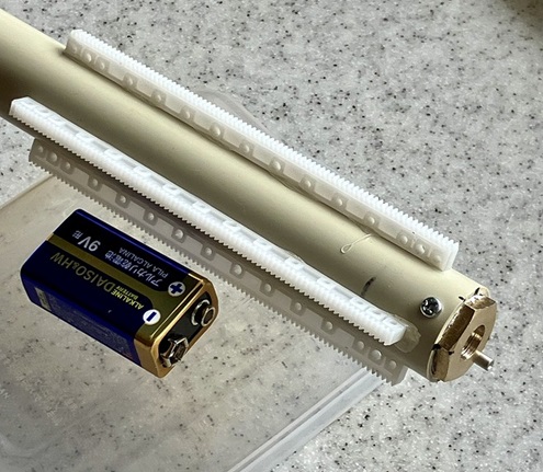
Figure 8. Coil form made with plastic toy parts glued to PVC conduit
An online calculator*9 was used to optimize the coil. The “Q” using 0.8 mm copper wire was higher than with 1.2 mm aluminum, and much higher than with stainless steel wire. I don’t have a 3D printer, so I made a threaded coil form by gluing four plastic toy car parts (Figure 8) to 26 mm PVC conduit. The parts have notches every 1 mm and make a square coil form 33 mm on a side and 125 mm long. The fixed 12 µH section has 19 turns with 1 mm spacing and the variable 13 µH section has 29 turns, skipping notches so the bypass cliplead touches only one wire (Figure 9). The calculated “Q” of the coil is 360, and inductance can be adjusted from 0 to 13 µH or from 12 to 25 µH depending on which end the cliplead is attached to. It works with either length whip antenna and is light, strong, and easy to adjust.
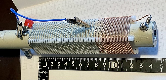
Figure 9. Completed two-section loading coil for either whip antenna. A wire through the PVC pipe connects the BNC center pin to the bottom of the coil.
A brass plumbing reducer (Figure 10) was redrilled and tapped for M10 to mount the threaded whip antenna to the 22 mm inner diameter of the PVC conduit. Depending on what arrived from China, I used either 1/2” x 1/8” NPT or 3/8” x 1/8” NPT reducers, or a machined aluminum adaptor. Holes are drilled and tapped for M3 screws to fasten the pieces together and make the coil connection. (Figure 11).
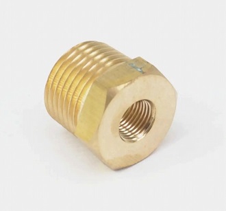
Figure 10. Plumbing reducer used for the whip antenna adaptor.
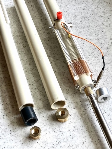
Figure 11. Different ways of making a strong mounting connection for the whip antenna
A small choke with a T94-52 ferrite toroid and 11 turns of small coax (Figure 12) isolates the capacitance of the operator and transceiver and makes tuning more repeatable. The antenna consists of only the coil, whip, bypassing cliplead, radials and the choke. Connections are made with a female BNC connector mounted in the PVC below the coil and a banana jack for the radials soldered to the BNC ground terminal. Thin insulated radials are attached to one banana plug, and the radio can be connected by any length of 50-ohm coax. The inside diameter of the PVC conduit is 22 mm, allowing many kinds of support to be used.
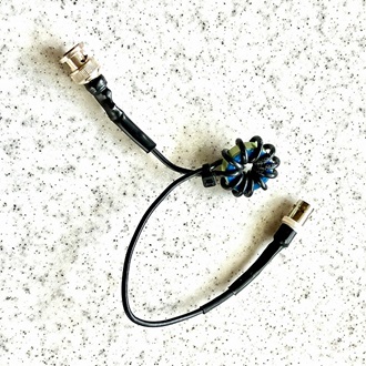
Figure 12. Isolation choke
The inductance of the coil sections is critical, but is adjustable with the bypassing cliplead. If you build one yourself, use the same parts and dimensions as I have, or measure the coil inductance as you add turns, or just check the resonant frequency with whip and radials attached. The 13 µH coil can be omitted if you plan to use only the longer whip*10. Connectors for the feedline and radials can be any type you prefer. You can experiment with the radials, but I suggest starting with 2 to 3 meters length.
Testing, testing:
The high Q and sharp resonance makes it easy to find the right place on the coil to bypass turns, or to shorten the whip for tuning the higher bands. I first listen for maximum receive noise and then tune accurately with an antenna analyzer or internal VSWR meter. The settings are quite repeatable even for different ground types. I found little difference with radial lengths from 2 to 3 meters, and get low and repeatable VSWR with the radials just lying on the ground, making it very quick to get on the air. Similar to a mobile antenna magnetic mount, the radials are capacitively coupled to ground. Resonance depends mostly on the vertical length and loading coil inductance, so increasing the radials' length or capacitance to ground past a certain point does not affect resonance or performance.
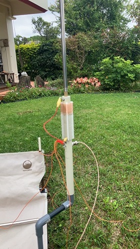
Figure 13. The new antenna on its first test in my garden
The first on-air tests were made in my garden, a poor location shielded by the house, but I made several QRP contacts. After the Fiji mini-expedition, I made comparison tests of the new verticals with three of my other portable antennas. All five antennas were set up in a park about one kilometer from another station*11 and signal strength were measured using an SDR receiver and multi-band dipole. Steady carrier transmissions using 5 watts were made each time, with received signal strengths from 40 to 50 dB above the noise level, or approximately S6 to S9*12.
The results are shown in the table below with the strongest signal on each band normalized to 0 dB. The other numbers indicate the average of three transmissions for each antenna relative to the strongest on that band. (Empty cells indicate the antenna did not cover that band.)
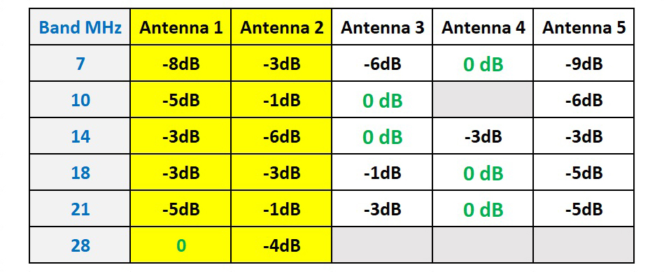
Antenna 1: 2.5-meter telescopic whip with the loading coil described above.
Antenna 2: same as Antenna 1, with the 5.7-meter whip.
Antenna 3: Magloop rotated for maximum received signal.
Antenna 4: 1/4-wavelength parallel vertical VGP with elevated radials for 14, 18, and 21 MHz and horizontal wire for 7 MHz.
Antenna 5: 16-meter “random” end-fed inverted-V using a 9:1 balun and autotuner.
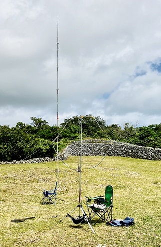
Figure 14. The magloop and Chair-tenna are effective, but take longer to set up
The test replicated normal portable operation, but could not control for directionality, height above ground, or polarization. The full quarter-wave “chair-tenna” and the magloop were strongest but, except for the short whip on 7 MHz, the verticals were within one S-unit of the best antenna. On 21 and 28 MHz the short whip was stronger than the long whip, possibly because of slightly different elevations.
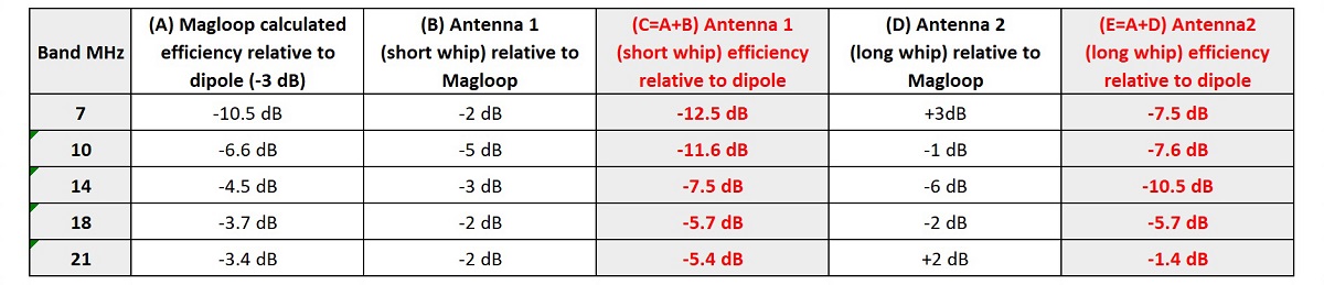
Online calculators*13 can show the efficiency of an ideal magloop relative to a dipole, based on its dimensions. Using the calculated magloop efficiencies (minus 3 dB from each because my magloop is not ideal) and the signal strengths from the other antennas, the efficiency of the new verticals relative to a dipole can be estimated. The verticals are one to two S-units less efficient than a full-size dipole, which is not much considering their relative sizes.
Conclusion:
This portable antenna meets all my objectives. Performance disadvantages are outweighed by practicality for portable operation, and it could also be a “stealthy” antenna if necessary. It is effective on bands from 7 to 28 MHz, occupies almost no ground area, packs in a short bag weighing 370 or 265 grams including a whip, radials, and choke. I can set it up and be on the air in a minute or two. On 7 and 10 MHz, the 4 to 5 dB advantage of the longer whip could make a difference in making a contact, but the shorter whip performs almost as well so I would usually choose it, especially on a windy day.
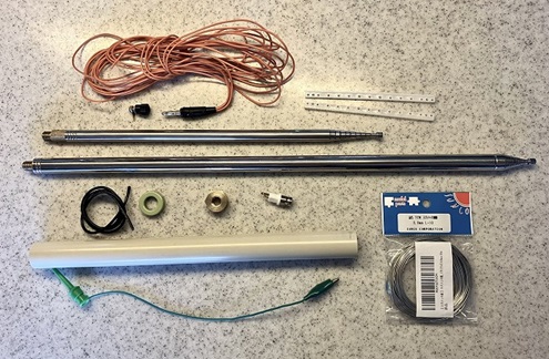
Figure 15. All parts for the antenna
It can be built at very low cost using basic tools. The cost of materials including the coil form and whip antenna adaptor, wire, radials, connectors, and choke is around JPY 3000 (US $20) for one antenna, and the telescopic whips cost US $15 or $20. It would be especially economical for a group or club to purchase parts to build several antennas.
Parts List and Sources:
2.5 or 5.7-meter telescoping whip antenna (AliExpress, etc.)
0.8 mm tin plated or bare copper wire, 5 meters (Amazon)
Plastic toy car steering parts
https://ja.aliexpress.com/item/1005006151643605.html?spm=a2g0o.order_list.order_list_main.68.50c3585aZeNexc&gatewayAdapt=glo2jpn
26 mm OD PVC conduit (DIY store)
Brass Hex Bushing Reducer pipe fitting Male 1/2” or 3/8” NPT to Female 1/8” NPT (DIY store or AliExpress)
T94-52 ferrite toroid (AliExpress) and 50 cm RG174 or RG178 coaxial cable
Banana jack and plug
2 small alligator clips
BNC female or other coax connector
M3 x 8 screws
8-10 meters thin insulated wire for radials and jumper
Tools:
9.5 mm and 2.5 mm drills, M10 and M3 taps, vise, soldering iron.
References:
*1 The monthly FB News, April 2023.
*2 For example, https://www.qsl.net/sp9hzx/diy.html
*3 For example, https://www.66pacific.com/calculators/coil-shortened-vertical-antenna-calculator.aspx
*4 For example, https://ventenna.com/files/Radials.pdf
*5 The ARRL Antenna Book 18th edition. American Radio Relay League, Inc. 1997
*6 Dale Hunt, WB6BYU Understanding the Quarter-Wave Groundplane Antenna
https://practicalantennas.com/designs/verticals/gp2/
*7 Thanks to Rob, DM1CM for the SOTA data.
*8 I use a 1/8 wavelength VGP on 3.5 MHz with a matching network at the base with good success in my fixed station. (See the monthly FB News, January 2022.)
*9 https://dxc.pi4cc.nl/tech-info/calculators/opticoil/
*10 The 5 MHz (60 meter) band can be tuned with the long whip and full inductance if you are in a country where it is used.
*11 Thanks to Rich, JS6TRQ.
*12 One S-unit is usually equivalent to a change of 6 dB signal strength.
*13 https://www.66pacific.com/calculators/small-transmitting-loop-antenna-calculator.aspx
From Steve's Workbench backnumber
- Another SOTA antenna, and some thoughts on antenna efficiency
- The Versatile Vertical Delta Loop
- An improved portable Magnetic Loop “Magloop” Antenna
- Small wonder: The Evolution of the uSDX and other QRP transceivers
- I learned about relays by rebuilding some Workbench projects
- Cheap but effective satellite antennas – Part 2: Directional antennas
- Cheap but effective satellite antennas – Part 1: Omnidirectionals
- 18/24 MHz rotatable dipole,“Random-length”, end-fed, multiband antenna
- My shack was a jungle of cables! The solution was a remote antenna switching system.
- Remote Antenna Tuners – Part 2 – Designing, Building, and Testing a Remote Antenna Matching Unit
- Remote Antenna Tuners – Part 1 – Why Use A Remote Antenna “Tuner”