


From Steve's Workbench
Cheap but effective satellite antennas
Part 2: Directional antennas
Last month’s article was about omnidirectional antennas for amateur satellite (VHF/UHF) communication. This month we look at two types of directional antennas that are cheap, fun to build, and very effective for satellite work. More construction details can be found online when you are ready to start building.
A directional antenna focuses RF energy in certain directions, resulting in “gain” over an isotropic antenna on transmitting and receiving (Figure 1). The directional nature of these antennas helps reduce interference signals, but usually we just want gain so we can transmit stronger signals and receive weaker ones.
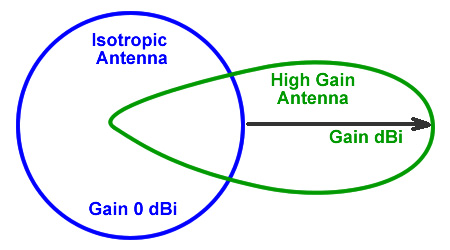
Figure 1. Directional antennas focus radiated power. Gain over a dipole is written as dBd or just dB, and is 2.15 dB less than gain over an isotropic antenna.
>>>>> Take The Antenna Knowledge Quiz! <<<<<
Q1. NAME THREE KINDS OF DIRECTIONAL ANTENNAS
Was your first answer “Yagi”? Yagi-Uda antennas have been popular with hams for decades, although few know their interesting history. The Yagi-Uda and close relatives such as cubical quads, Moxons, and hexbeams use one or more parasitic (passive) elements to change the phase of radiation from a driven element, reinforcing it in one direction and reducing it in others. Somewhat different methods are also used to produce a directional phase relationship, including W8JK (HB9CV) arrays, log-periodic antennas, and reflector and horn antennas for very short wavelengths.
The Yagi-Uda’s continuing popularity is partly due to the directivity and gain that can be achieved with relatively small size. As a young ham wanting a big signal on 2-meters, I saved up for a 32-element array like the one in Figure 2, but it did not survive the first windstorm. I replaced it by a 15-element Yagi that had the same forward gain, but only a fraction of the wind load.
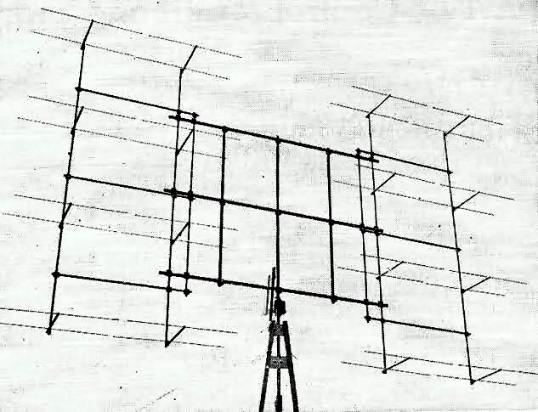
Figure 2. A 32-element collinear array for 144 MHz. These were used in early radars.
“Traveling wave” directional antennas work differently, and this group includes the helical antennas discussed later, as well as long-wire antennas for HF such as the rhombic, Vee, and Skyloop, which have narrow radiation lobes that give directivity and gain.
Let’s take a closer look at Yagi-Udas. The arrangement of elements is familiar to hams but the theory behind it is quite complex.
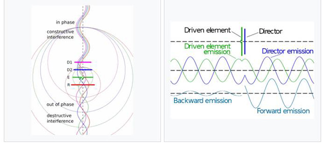
Figure 3a and 3b. Schematic representations of the phase relationships in a Yagi-Uda.
A slightly longer reflector element is placed behind a driven dipole element, opposite the direction of intended transmission (Figure 3). Shorter directors are placed in front of the driven element. These passive (or parasitic) elements receive and then re-radiate energy from the driven element, so that waves in the forward direction are in phase and waves in the reverse direction are out of phase. The forward waves add together while the backward waves partially cancel.
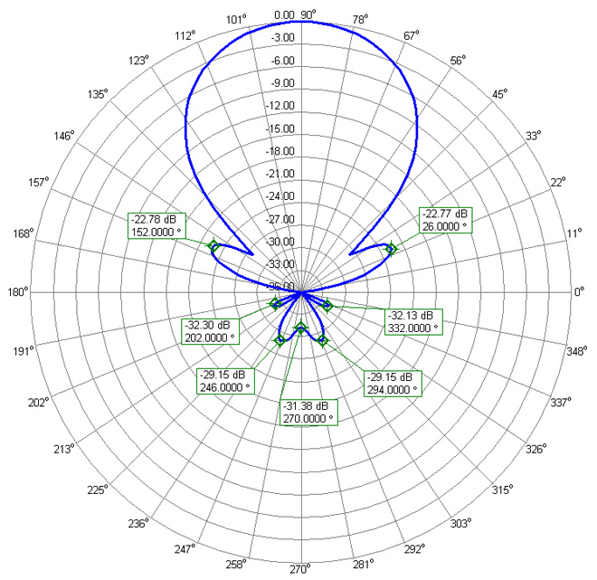
Figure 4. Horizontal radiation pattern of a 7-element Yagi-Uda showing good F/B and small side lobes
Bandwidth, front-to-back (F/B) ratio and noise figures are all important antenna qualities for radio communications, but hams usually want high forward gain above all. Several features of the Yagi-Uda antenna affect its gain, primarily the number of elements in the antenna. Adding the reflector gives around 4 to 5 dB gain, the first director adds about 2 dB, and then about 1 dB is added by each additional director. Element spacing has an impact on gain with wide spacing between elements giving more, up to some optimum spacing. The positions of the reflector and first director are the most critical. The gain of a Yagi array therefore increases if the boom is made longer, but the general need to keep antennas small means that few HF Yagi-Udas are truly optimum design. At VHF and UHF though, many more directors can be used because the elements and spacing are small. The excellent directional pattern of a 7-element, long boom VHF Yagi is shown in Figure 4.
Antenna feed impedance is another important variable. A resonant driven element in a Yagi can have an impedance much lower than 50-ohms. Element spacing affects the impedance to a great degree, so adjusting spacing is a design technique for obtaining the desired impedance. The “OWA” (Optimum Wideband Antenna) Yagi has 50-ohm feed impedance, and is easily recognized by the first director being close to the driven element.
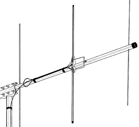
Figure 5. The hairpin or beta match connected to the driven element.
Other methods often used to match feed impedance include the hairpin or beta match (Figure 5), and the gamma match (Figure 6). These have drawbacks: hairpin matches must be made very accurately, and gamma matches have sliding contacts, sometimes a series capacitor, and must be adjusted for low VSWR. Another method is the “DK7ZB match” (Q-match), which uses a short transmission line impedance transformer.
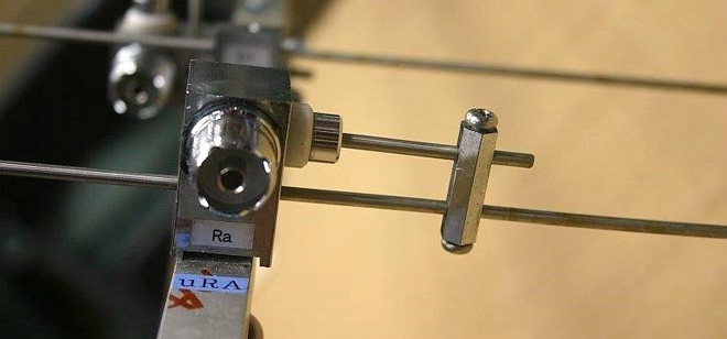
Figure 6. Gamma match on a 435 MHz satellite antenna.
DIY antenna builders have many options, but I choose designs that are easy to build, work well without much tinkering, and have excellent performance and reliability. One such antenna that checked all those boxes is my 50 MHz OWA Yagi that is fed directly like a dipole.
For portable satellite work, the commercially available “Arrow” antenna is very popular and is duplicated by many builders. Small Yagis for 2-meters and 70-cms are mounted on one boom, which is light enough to aim by hand and is easy to transport. The two Yagis can be perpendicular or in the same plane. It uses gamma matches, but I will describe a simplified version that is my “go-to” satellite Yagi.
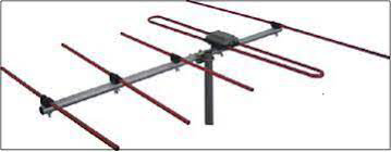
Figure 7. Yagi with a folded dipole driven element.
An old approach to matching a Yagi uses a folded dipole driven element. Its free-space 300-ohm impedance is lowered by the passive elements so it is easily matched to coax or twinlead. For decades, TV antennas looked like the Yagi in Figure 7. My favorite homebrew Yagi design uses a driven element that is three-quarters of a folded dipole with about 150-ohms impedance in free space (Figure 8). As other elements are added they lower the impedance to around 50 ohms. Published in CQ Magazine by WA5VJB in 2006, it became known as the Cheap LEO (Low Earth Orbit) Yagi. Construction is very simple because the center of the long side of the J-shaped dipole is a voltage null that is connected to the coax shield, while the coax center conductor connects to the tip of the J. Solder connections eliminate coax connectors at the antenna.
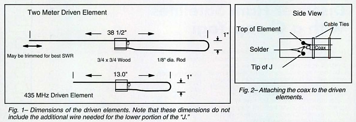
Figure 8a and 8b. The “Cheap LEO” J-dipole driven element is a clever way to feed a Yagi.
WA5VJB used computer modeling and field testing to get optimum element lengths and spacings for 2, 3, 4, and 6-element 144 MHz Yagis and 5, 6, 8, and 11 elements on 435 MHz. I built several “Arrow” type dual-band Yagis using lightweight square wood booms (Figure 9), which simplifies drilling perpendicular holes and eliminates the need for insulating the elements. The parasitic elements are aluminum tubing and the driven elements are made from brass welding rod that is stiff but easy to bend and solder. The 144 MHz Yagi needed only small adjustments, but the VSWR of the smaller antenna was very sensitive to small changes. Slightly bending the first director was an easier way to tune it to resonance than trimming the driven element.
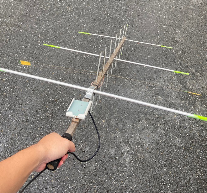
Figure 9. “Cheap LEO” version of the Arrow dual-band satellite antenna. The smartphone holder is so I can use a satellite tracking program.
The longest Cheap LEO that I built was originally 5 elements on 2-meters and 10 elements on 70-cms, but I later extended it by simply attaching a length of boom that held 2 more directors for 2-meters and 4 more for 70-cms. Mounted at fixed 20-degree elevation, I made hundreds of satellite contacts with it. Then came RS-44…..
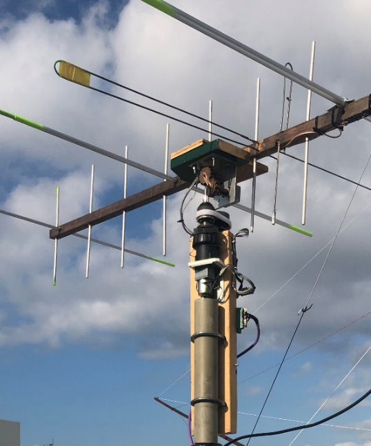
Figure 10. Another version: A longer version on a homebrew azimuth/elevation rotator. (A fun workbench project, but not really good for permanent outdoor use.)
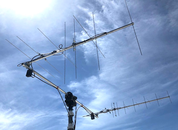
Figure 11. A commercial dual-band satellite antenna that can change polarization.
The Russian RS-44 linear transponder satellite was immediately popular with ham satellite DX’ers because of its large footprint, but its signal was subject to fading. Most amateur satellites use simple unipole antennas so there is signal loss due to cross-polarization as they spin, unless the ground station polarization is changed. Polarization fading is also caused by Faraday rotation as the signal passes through the atmosphere. Twisting a hand-held Arrow-style antenna can be fun (and amusing to onlookers), but a ground station requires switching between vertical and horizontal antennas or the compromise of circular polarization. Popular but rather expensive ground station antennas such as the M2 LEO-PACK (Figure 11), use relays and phasing lines to switch polarizations.
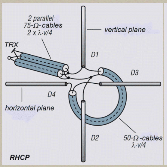
Figure 12. Circular polarization with two crossed dipoles.
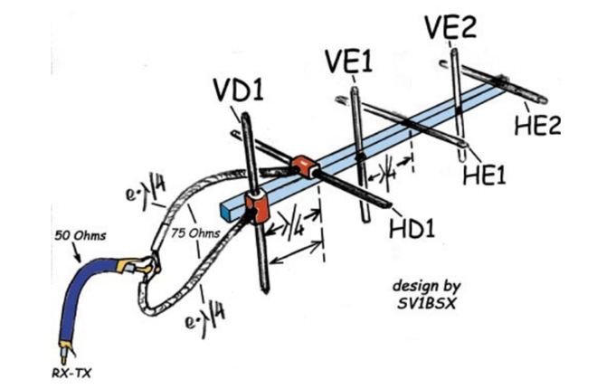
Figure 13. Circular polarization by positioning identical antennas apart on the boom.
Fortunately, right-hand circular polarization alone works well for the amateur satellites, simplifying the antennas considerably. It can be obtained by using crossed antennas with a 90-degree phase difference that can be created either by an electrical delay (Figure 12), or a physical delay (Figure 13). The second method makes it easier for the DIY builder to get the exact phase relationship. I made two perpendicular 6-element 144 MHz Yagis using the “Cheap LEO” design, offset by 52 cms (Figure 14). Using the 75-ohm coax matching sections shown in both figures, no adjustments were needed to get low VSWR in the satellite sub-band.
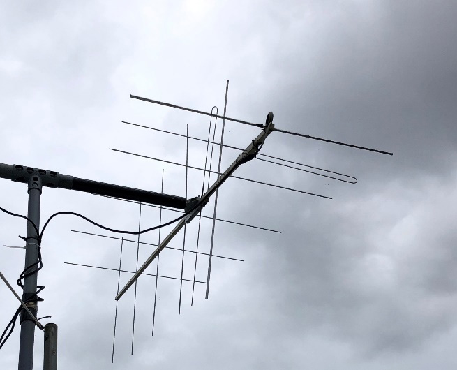
Figure 14. My circularly-polarized Yagis for 144 MHz.
Now I also needed a circularly-polarized antenna for 70-cms. I thought a crossed Yagi might be difficult to tune, and anyway I was bored with Yagis. A local ham suggested I try a helical antenna, which are widely used for space communications and have high gain and wide bandwidth. I found it had been invented by a radio ham, (W8JK of the phased array) and also that a former professor of mine had made important improvements to it in the 1960’s. Best of all, it was very simple (Figure 15) and looked easy to build.
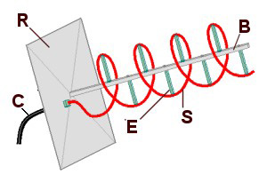
Figure 15. Main parts of the helical antenna: (B) Central support, (C) Coaxial cable feedline, (E) Insulating supports for the helix, (R) Reflector ground plane, (S) Helical radiating wire.
Helical antennas operating in the “axial” mode have a radiation pattern that is directional along the axis, but with stronger side lobes than Yagi-Udas (Figure 16). The axial mode is obtained by making the circumference of the helix about one wavelength and the spacing a quarter-wavelength. The more turns, the greater the gain. A helix by itself radiates in both axial directions, so a reflector is needed. The feed impedance is between 100 and 200 ohms.
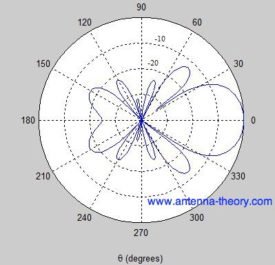
Figure 16. Typical radiation pattern of a helical antenna in horizontal or vertical plane.
Describing the helical antenna is quite different from knowing how it really works. It radiates in a non-resonant traveling wave mode, in which rotating electrical and magnetic fields generate a circularly polarized beam off the ends of the antenna. I can visualize phase reinforcement happening along the axis similar to the Yagi-Uda because of the one wavelength circumference and quarter-wavelength turn spacing. It seems obvious the helical shape results in circular polarization, but my imagination stops there, so let’s please go back to my workbench!
Construction is quite simple since there is only the conductive helix, a crescent-shaped matching stub, and a small reflector. It was new to me, but I enjoyed figuring out how to attach all the pieces. To keep it light weight I used aluminum wire and a 25-mm square wood boom with wood dowels to support the helix. The boom fits into a hub on the plywood reflector frame so the position of the helix and the copper matching section can be adjusted with respect to the mesh reflector (Figure 17).
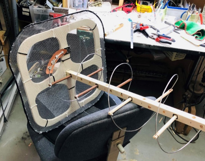
Figure 17. The helical antenna showing the first turns, the reflector, the copper matching line, and the famous workbench.
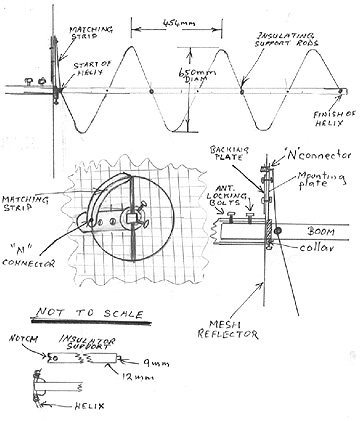
Figure 18. Details of a 144 MHz helical antenna built by VK5ZAI.
Figure 18 is from an article on the AMSAT-UK website. The dimensions are for 144 MHz, but construction and adjustment is similar to my 435 MHz version. Online calculators give the helix diameter, spacing, and wire length for other given frequencies. 14 dB of gain from 9 turns, on a 1.8-meter long boom seemed practical. I bought some 2.5-mm aluminum wire packaged in a coil that was close to the helix diameter. That made it very easy to assemble. I first made a solid connection to the copper stub, slowly pulled the coil outward like a Slinky and fastened the wire to the dowels (Figure 19).
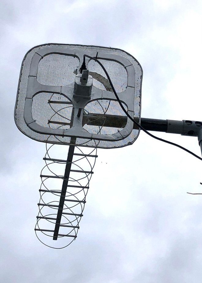
Figure 19. Showing the reflector hub adjustment for boom position and rear coax connector.
A PL-259 connector is mounted on the plywood frame with the ground connected to the reflector and the center soldered to the copper matching stub (Figure 19). I had to make the matching section narrower in order to get perfect VSWR from 400 and 500 MHz (Figure 20). The spacing between the copper stub and the reflector was very sensitive, but once adjusted the tuning was stable and did not change when the antenna was mounted on the mast.
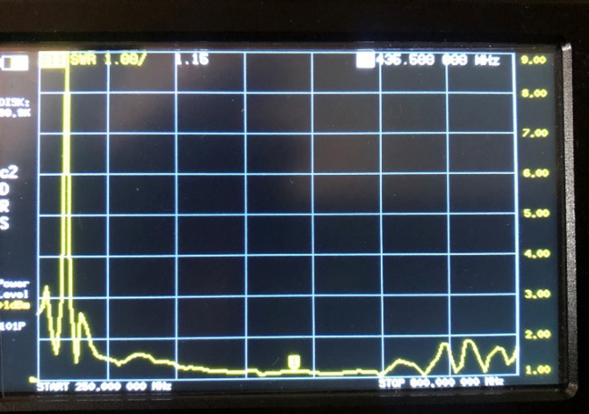
Figure 20. Broadband VSWR adjusted by positioning the boom.
The helical antenna works very well. I rarely need a preamplifier to hear the RS-44 downlink as I did with the Yagi, and fading is much less. The 2-meter crossed Yagi also performs well. I mounted both antennas on a fiberglass cross-boom, using PVC pipe and fittings to couple it to the vertical rotating mast. With a fixed elevation of around 15 degrees, I have made two-way contacts through RS-44 over distances of 6000 kms.
The crossed Yagi and the helical antenna is a high-performance, low-cost combination for an amateur ground station, and were a lot of fun to build. I got all the materials (except the fiberglass cross-beam) at local DIY stores, and the total cost was a small fraction of a commercial antenna system.
References:
Figure 1: https://www.ahsystems.com/EMC-formulas-equations/images/Antenna-gain-dBi.png
Figure 2: https://www.rfcafe.com/references/qst/images4/beam-antenna-144-mhz-qst-december-1953-2_small.jpg
Figure 3a and 3b: Wikipedia
Figure 4: https://antennas-amplifiers.com/product/4meter-antenna/70mhz-7-element-antenna-4-meter-yagi/
Figure 5: https://mfjenterprises.com/products/vb-23fm
Figure 7: https://www.tutorialspoint.com/antenna_theory/images/construction_yagi_uda_antenna.jpg
Figure 8a and 8b: https://www.wa5vjb.com/yagi-pdf/cheapyagi.pdf
Figure 12: https://www.qsl.net/dk7zb/Cross-Yagi/crossyagi.htm
Figure 13: https://www.qsl.net/sv1bsx/antenna-pol/polarization.html
Figure 15: Wikipedia
Figure 16: https://www.antennatheory.com/
Figure 18: AMSAT-UK
From Steve's Workbench backnumber
- Another SOTA antenna, and some thoughts on antenna efficiency
- The Versatile Vertical Delta Loop
- An improved portable Magnetic Loop “Magloop” Antenna
- Small wonder: The Evolution of the uSDX and other QRP transceivers
- I learned about relays by rebuilding some Workbench projects
- Cheap but effective satellite antennas – Part 2: Directional antennas
- Cheap but effective satellite antennas – Part 1: Omnidirectionals
- 18/24 MHz rotatable dipole,“Random-length”, end-fed, multiband antenna
- My shack was a jungle of cables! The solution was a remote antenna switching system.
- Remote Antenna Tuners – Part 2 – Designing, Building, and Testing a Remote Antenna Matching Unit
- Remote Antenna Tuners – Part 1 – Why Use A Remote Antenna “Tuner”