


From Steve's Workbench
I learned about relays by rebuilding some Workbench projects
Relays are one of the simplest and most widely used electrical components. They come in many shapes and sizes, but all have the same function – to complete a secondary circuit at a distance from a primary circuit. The word itself goes back to when important messages were carried by runners, and in the 19th century the electromagnetic relay became the basis of the telegraph and railway signaling. The American Radio Relay League (ARRL) was organized to pass messages rapidly across the continent back when radio hams could only transmit over short distances. In elementary school we had the usual relay races, but we were also introduced to logic circuits by a board full of relays, buttons, and lamps that could play tic-tac-toe.
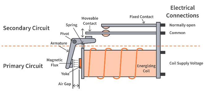
Figure 1. The basic parts of all electromagnetic relays are still the same.
I am often surprised to see many relays on circuit boards in modern radios, looming above tiny surface-mount parts. They are much smaller than the old clacking things with powerful coils and fat contacts (Figure 1) but they still operate on the same principle. Solid-state devices are used when very fast switching is needed, but there are tasks where the old electromagnetic design is superior, especially for switching RF power.
I recently rebuilt three projects that I described in the monthly FB NEWS. They all are related to antennas, and they all use relays. I found that getting the best results from simple relays can require very careful design and construction.
A. The magloop portable antenna. My first monthly FB NEWS article was about a Japan Castles On The Air (JACOTA) activation in Okinawa, but the highlight was a homebrew magnetic loop (magloop) antenna. I had built magloops which were not very successful, but I was inspired to try again by a blogpost showing a portable loop that folded like an old-fashioned carpenter’s rule (Figure 2).
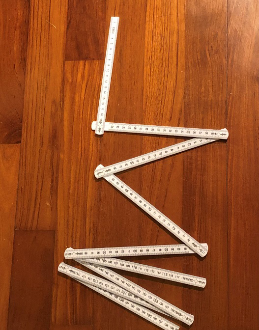
Figure 2. The carpenter’s rule was my inspiration for the folding magloop antenna.
To cover 7 to 21 MHz, I made the loop from four 1-meter lengths of light aluminum bar stock. The challenge was keeping the resistance of the folding joints very low, but high compression on a large contact area (Figure 3) worked well. The electrical performance was good, but it was top-heavy and blew around in the wind. That made tuning the variable capacitor by hand quite difficult, and I also had to lower the support mast to change bands.
I coupled a small DC motor to the tuning capacitor and installed small relays to switch fixed capacitors for changing bands (Figure 4). These were controlled from a remote box that included a VSWR meter. Now I could change bands and tune from my operating position, but I found two more problems on my next SOTA activation. I needed to pound a stake in the ground to support the mast, but it was impossible on the rocky mountaintop. And carrying 1 meter lengths of aluminum was hazardous to other climbers and to passengers on the crowded ferry.
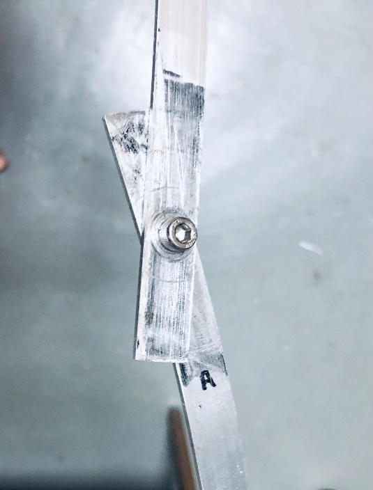
Figure 3. Folding joints relied on large contact area and high pressure.
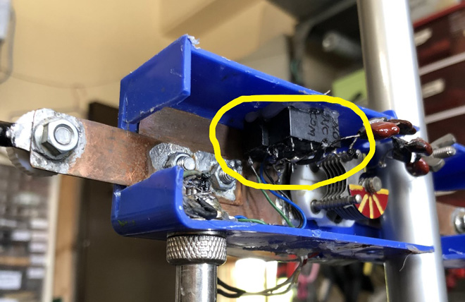
Figure 4. The relays switch fixed capacitors in parallel with the small variable capacitor to cover 7 to 20 MHz.
I replaced the aluminum strips with 5D-FB coaxial cable, which is a good lightweight conductor that is rigid enough to hold a round shape but can be coiled for transport. I eliminated the ground stake with a small camera tripod and an accessory pouch that can be filled with stones or sand from the site (Figure 5). The magloop, cables, and tripod weigh exactly one kilogram, and they fit in a small carry bag that will not bother innocent bystanders.
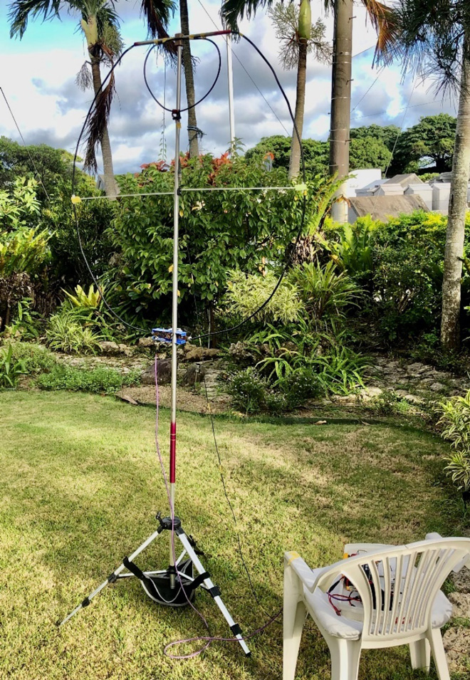
Figure 5. 5D-FB coax is now used for the main loop, with remotely controlled tuning and a lightweight tripod. (Note - I have rebuilt it again since taking this photo!)
The relays were a problem though. When I used a toggle switch at the loop for switching the fixed capacitors in parallel with the varicap (Figure 6), it could be tuned up to 22 MHz. Relay switching the capacitors worked correctly, but raised the minimum capacitance so it could not resonate higher than 20 MHz. I lost the 15 meter band because of small capacitance and inductance added to the resonant circuit.
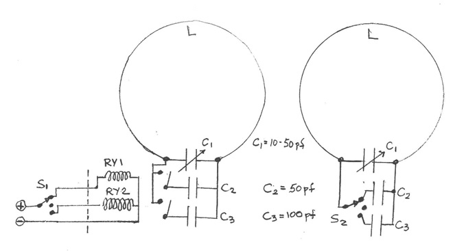
Figure 6. RY1 and RY2 switch in fixed capacitors (left), but the minimum capacitance of the resonant loop circuit was increased compared to the toggle switch used originally (right).
B. Remote HF antenna switch. My next rebuild was the remote antenna switch I described several months ago. I used it many times a day with 100 watts, but when I tested it with 800 watts, some of the 10-ampere (DC) relay contacts were not happy. I bought some inexpensive DPDT relays with 16-ampere (DC) contacts to replace eight of the original relay circuits, using solid copper wiring on perfboard (Figure 7). The combined 32-ampere capacity and solid wire connections easily passed QRO tests, but I was concerned that the larger relays might affect the VSWR.
If an antenna or something near it increases VSWR on the transmission line, this results in loss from the entire line back to the RF source. On the other hand, if the VSWR “bump” is close to the RF source, line loss will be low but high VSWR might still cause problems with the transmitter or ATU.
Using a calibrated analyzer, I measured a 50-ohm resistive load through the relay box before and after changing the relays. The VSWR at 3.5 MHz was 1.04:1 through one set of the original relay contacts versus 1.07:1 with the new relays. VSWR on 28 MHz was 1.30:1 with both the old and new relays. The “worst-case” measurement was at 28 MHz through four sets of contacts in series (to switch antennas in a phased array). VSWR through four of the larger relays was 1.65:1 versus 1.40:1 with the original ones. However, since this circuit is only used below 10 MHz and the antenna switch is located near the transceiver, the losses in the connecting coax are negligible. I did not measure isolation or insertion loss, but the bottom line is that the high-power relays and solid wire connections in the remote antenna switch had no practical effect on VSWR.
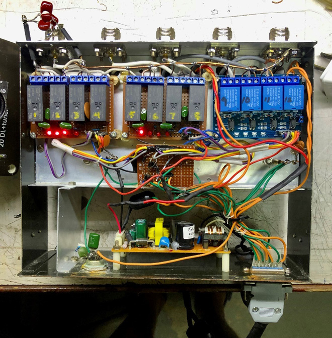
Figure 7. Higher power relays 1-8 replaced smaller modules in the wall-mounted remote antenna selector. (Small capacitors at top left are for matching the phased 7 MHz antennas.)
C. The satellite antenna relay. It is much more difficult to achieve low VSWRs with ordinary relays at VHF and UHF because of their relative size and internal design. In my satellite station, I have to switch from a pair of directional antennas to a pair of omnidirectionals when the satellite is at high elevation. The most practical way to do that is with a DPDT relay where the antenna cables enter the shack.
A variety of relays is available that work well at UHF and low microwaves, but power handling ability becomes expensive. Miniaturized SPDT coaxial relays by Panasonic operate up to 3 GHz (Figure 8), can switch 10 watts and cost about US$15, or by Axicom which cost $23 and can switch 50 watts. Large traditional coax relays (Figure 9) can handle 300 to 1500 watts up to 2.5 GHz, and cost $120-$200.
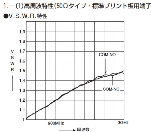
Figure 8. An inexpensive relay by Panasonic has low VSWR at UHF and switches 10 watts.
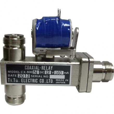
Figure 9. A typical high-power SPDT coaxial antenna relay for UHF.
For changing satellite antennas, I had mixed results with relays similar to those I used on HF. A well-known DIY-er, W6PQL, found that some cheap relays can handle considerable power with low VSWR and good isolation up to 500 MHz, by using a carefully designed circuit board and small compensating capacitors (Figure 10a). I don’t have the equipment to produce etched circuit boards (it is high on my priority list), and my copy of this circuit board using point to point wiring (Figure 10b) was a failure, with VSWR reaching 2.7:1 at 430 MHz.
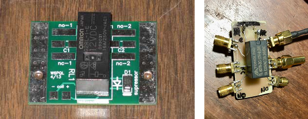
Figures 10a and 10b. W6PQL’s relay and PCB for UHF (left). C1 and C2 are small compensating capacitors that improve VSWR and isolation. My poor attempt to duplicate it (right) had very high VSWR.
With the same Omron relay that W6PQL used, I made a shielded box using coax cable for direct internal connections (Figure 11). The moderate VSWRs seen in Figure 12 might be due to random capacitance or resonance, which probably would be hard to reproduce. I used this unit successfully for satellite antenna switching with slightly high VSWRs, but again, the impedance “bump” affected only short jumpers to the transceiver, and not the antenna feedlines.
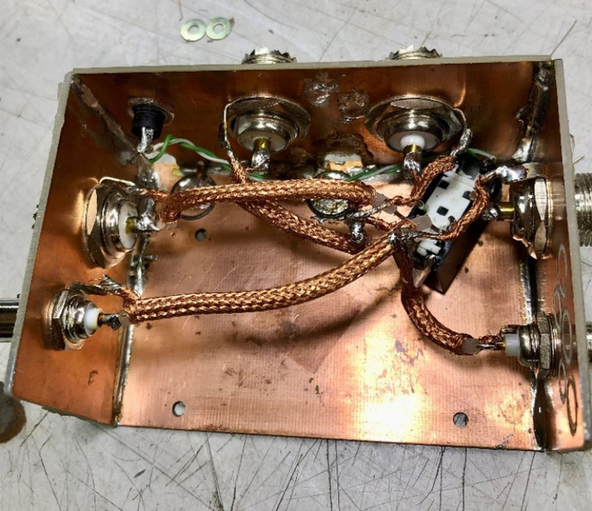
Figure 11. I used a cheap DPDT relay to switch VHF and UHF satellite antennas.
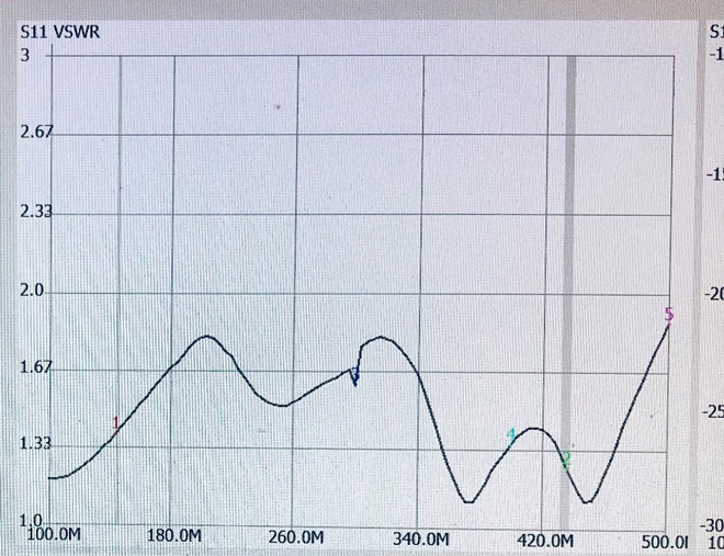
Figure 12. Dummy load measured through the shielded relay in Figure 10. The low VSWR on 70 cms is quite good, but probably was a lucky accident.
Accurate measurement of VSWR and other transmission line parameters at UHF is quite challenging with amateur-grade equipment. Even short coax jumpers and directional couplers can affect the impedance. Figure 13 shows VSWR measured through a good military grade UHF relay with two short jumpers. This is an RF path that should be very “flat”, but it means that it is difficult to know how much my homebrew relay actually contributed to the VSWR when I measured it alone.
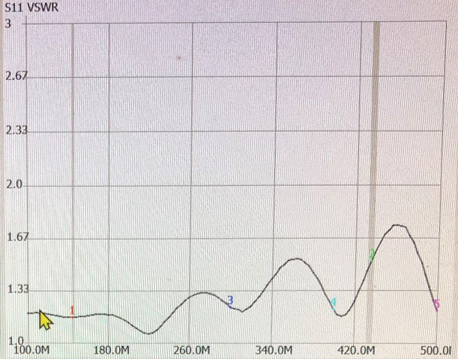
Figure 13. Dummy load VSWR measured through a high quality relay. Even short coax jumpers and connectors introduce impedance discontinuities.
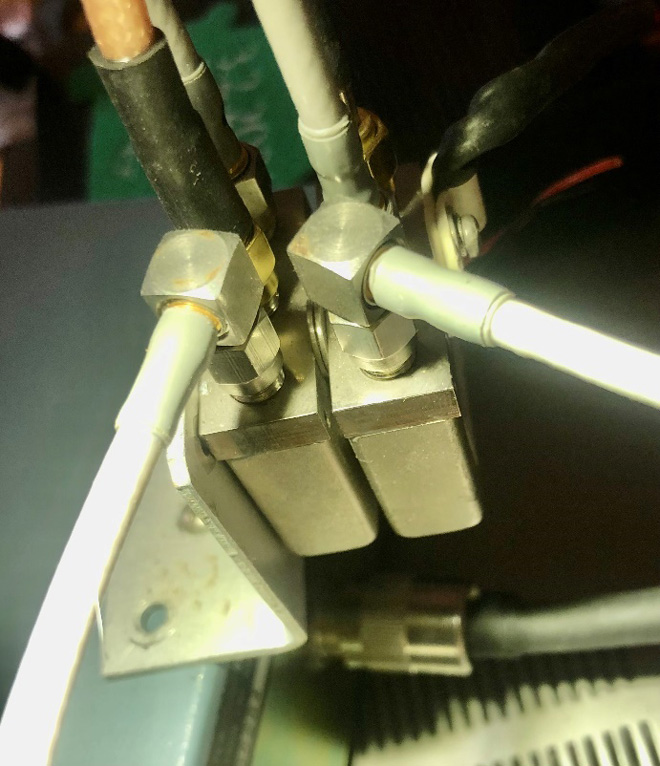
Figure 14. Good military-surplus UHF SPDT relays now do the satellite antenna switching.
The A, B, C’s of what my amateur mistakes taught me: A) Small conventional relays and their connections introduce stray inductance and capacitance, which can be a problem even at relatively low frequencies. B) In other applications slightly increased VSWR might be unimportant, and inexpensive relays can be used to switch high power. C) For VHF/UHF medium-power applications, proper relays would not have cost much, AND I must start making my own PC boards.
I leave you now with a photo of a ham rig that uses many small relays. In the next article I’ll discuss this particular radio and why it caused a minor commotion in the QRP universe. (Spoiler: it is NOT the IC-705.)
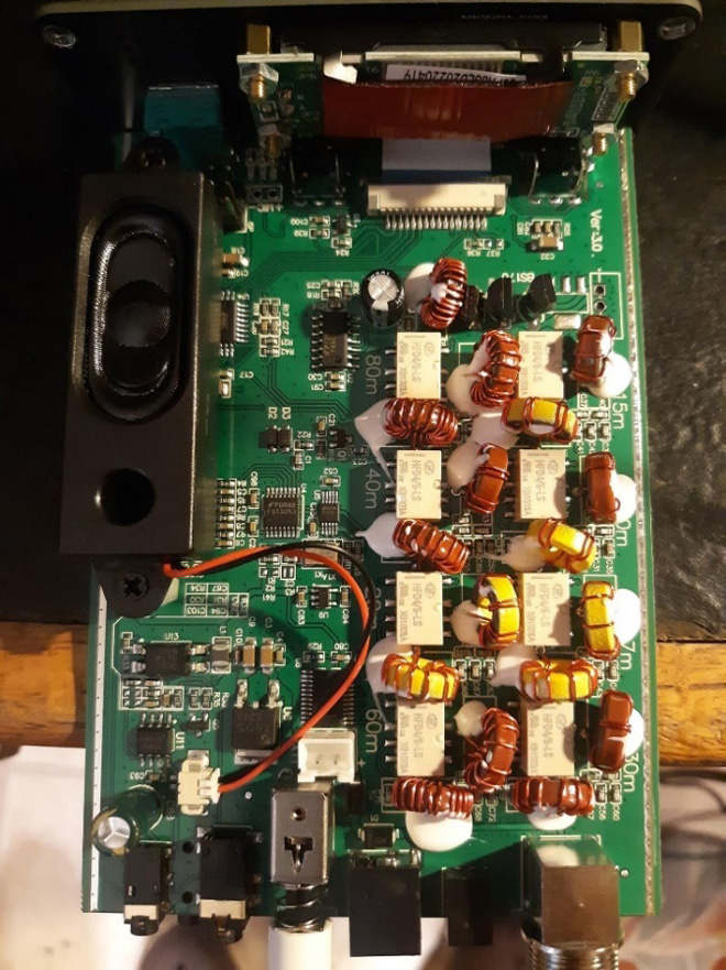
Figure 15. Relays (light yellow) are often used to switch RF components such as lowpass filters., and the inductors and capacitors in automatic antenna matching units. This truly “generic” QRP rig attracted much attention. Tune in next month to learn why.
Credits:
Figure 1. Circuitbread.com
Figure 8. Panasonic Inc.
Figure 9. TOHTSU Corporation
Figure 10a. W6PQL website https://www.w6pql.com/using_inexpensive_relays.htm
From Steve's Workbench backnumber
- Another SOTA antenna, and some thoughts on antenna efficiency
- The Versatile Vertical Delta Loop
- An improved portable Magnetic Loop “Magloop” Antenna
- Small wonder: The Evolution of the uSDX and other QRP transceivers
- I learned about relays by rebuilding some Workbench projects
- Cheap but effective satellite antennas – Part 2: Directional antennas
- Cheap but effective satellite antennas – Part 1: Omnidirectionals
- 18/24 MHz rotatable dipole,“Random-length”, end-fed, multiband antenna
- My shack was a jungle of cables! The solution was a remote antenna switching system.
- Remote Antenna Tuners – Part 2 – Designing, Building, and Testing a Remote Antenna Matching Unit
- Remote Antenna Tuners – Part 1 – Why Use A Remote Antenna “Tuner”