


From Steve's Workbench
Cheap but effective satellite antennas
Part 1: Omnidirectionals
Looking back on my Workbench articles in the monthly FB NEWS, I see they are all related to antennas rather than radios. It seems that the extreme miniaturization of components has made it almost impossible for us to build our own rigs. In the “old days” almost any ham who knew how to solder and turn a screwdriver could build a working receiver or transmitter from a kit or even from scratch. Nowadays our compact, sophisticated transceivers are mostly built by robots, and digital knowhow is more important for hams than burning solder, or even RF circuitry.
Fortunately for those of us who love to build, antennas have not (yet) been miniaturized. A wavelength is still a wavelength, and the materials are the same that were used in the past. In addition, we have easy access to design tools and collective knowledge unavailable before. Since getting re-licensed 8 years ago, I got up-to-date on antennas by reading, building, and trying them on the air. The most interesting part has been making high-performance antennas for amateur satellite work. I’ll discuss these in two installments, this month covering omnidirectional antennas, and next month directional high-gain antennas, all of which can be built very cheaply.
(I have not included references, but much more information on all the antennas discussed here can be found online.)
Omnidirectional antennas for terrestrial use
My previous articles were about HF antennas, but probably most hams use VHF and UHF (V/U). Reliable, noise-free “line-of-sight” contacts using low power is a big attraction of these bands, and repeaters help link up rural areas and mobile operators. Good FM transceivers have become very cheap, and the antennas are reasonably small. Let’s take a close look at the omnidirectional antennas (“omnis”) that are popular for local V/U work.
First, only an isotropic radiation pattern is truly omnidirectional. This is a theoretical concept used in physics and in relation to antenna gain and means radiation from the center of a sphere that is equally strong in all directions. For “terrestrial” V/U operation we want radiated power to go out to the horizon, not up and especially not down. This calls for antennas that are omnidirectional in the sense of directions (N, E, S, W) from a point on the ground. Simple vertical dipoles and ground plane antennas achieve this radiation pattern. Figure 1 shows the difference between an isotropic radiation pattern and what we usually think of as the omnidirectional pattern from a vertical dipole.
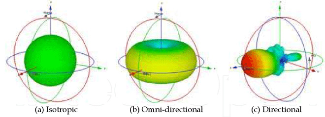
Figure 1. Antenna patterns modeled in 3D
A vertical antenna radiates perpendicularly to its axis, at low angles above and below horizontal (Figure 1b). There is a deep null directly above the antenna.
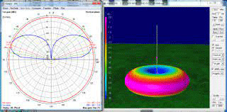
Figure 2. Radiation pattern of a vertical monopole
When the top part of the antenna is close to the ground or to a conductive ground plane, all the radiation is above that plane, as seen in Figure2. The vertical “monopole” is effective on HF bands for DX communication, because most power goes out at a shallow angle that can reflect off the ionosphere.
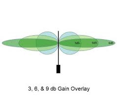
Figure 3. Gain in all horizontal directions is possible
Omnidirectional vertical antennas with gain over a simple dipole or monopole are very popular for V/U work. They radiate in all directions but focus radiated power into a narrower horizontal beam (Figure 3). This can be done by changing the length or number of the vertical elements.
Omnidirectional antennas for satellite use
Most amateur satellites contain a transponder that receives uplink signals from the earth on either VHF or UHF and retransmits them down on the other band. The onboard receivers are very sensitive, but the output power of the transponders rarely exceeds one watt (the ISS is an exception). These “low-earth-orbit” satellites are hundreds to thousands of kilometers away, so signals reaching earth are usually weak.
On the HF bands, signal polarization is modified by the atmosphere, earth, and other objects, and polarization matching is not critical. At VHF and higher frequencies, antennas at the transmitting and receiving sites should have the same polarization (vertical, horizontal, RH or LH circular) for maximum signal transfer. Fading is often caused by the satellite rotating and changing its antenna polarization. Some earth station antennas can change polarization to match, but an antenna with circular polarization can receive both horizontal and vertical polarization with only a slight loss of signal compared to an antenna with the correct polarization.
Low-earth orbit satellites (and aircraft) move across the sky at all azimuth and elevation angles. The amateur low-orbit satellites can be received with almost any antenna under good conditions, even with handy-talkie antennas that can be oriented to the position and polarization of the satellite. Directional antennas and PC software that tracks the azimuth (horizontal position) and elevation of the “bird” are used by serious satellite enthusiasts, but commercially-made high-gain antennas and specialized rotators can be expensive. Simpler, less costly omnidirectional antennas can also be used to make satellite contacts.
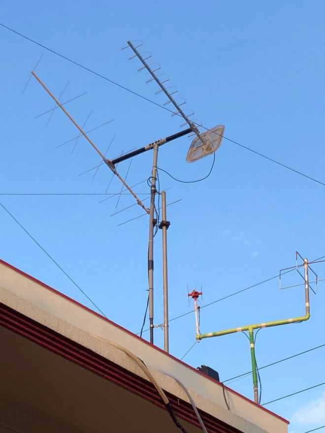
Figure 4. My “hybrid” fixed-elevation directional antennas and the omnis
I use a “hybrid” antenna setup (Figure 4), with directional antennas to track the satellite azimuth at a fixed elevation. That covers a 360-degree “doughnut” from 0 to around 45 degrees elevation. If the satellite goes higher, I switch to a pair of omnidirectional antennas to fill in the doughnut hole.
This project saved me a little money but provided a double dose of building fun and lessons learned.
Omnidirectional antennas used for satellites therefore need approximately equal gain in every upward direction, or half the pattern of a true isotropic antenna. Antennas optimized for this pattern have been developed for mobile devices, spacecraft having no fixed orientation, aeronautical communications, and amateur satellite work.
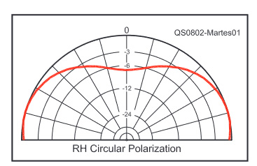
Figure 5. Ideal radiation pattern for omnidirectional satellite ground stations
As seen in Figure 2, vertical “omnis” for local communications have a deep null directly overhead. Satellites are closest to earth as they pass toward the zenith, so lower gain overhead is acceptable but a deep null is not. An ideal pattern for low-earth orbit satellites and air-to-ground communications is shown in Figure 5. Here are some of the designs that achieve it:
Turnstiles
The simplest (nearly) isotropic omnidirectional antenna is the Turnstile, basically a pair of horizontal dipoles mounted at right angles and fed as shown in Figure 6. The radiation pattern (Figure 7) is not ideal because half the power is directed downward, but the Turnstile is the basis of many antenna designs with improved radiation patterns.
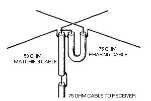
Figure 6. Basic arrangement for feeding and matching 2 antenna elements as a Turnstile
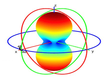
Figure 7. Radiation pattern from a simple turnstile antenna
Since only the upper half of the radiation pattern is wanted, a flat reflecting surface such as a metal screen or another pair of crossed dipoles is added below the turnstile (Figure 8). The reflected waves reinforce the upward radiation. This was the first omni that I built, but on the 2-meter version the wire mesh reflector caught the wind, making the structure unstable.
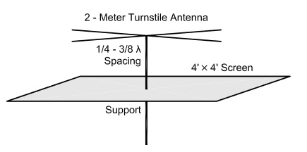
Figure 8. Basic turnstile with added reflector
Lindenblad
Lindenblad antennas are widely used for commercial and airborne communications. With its four folded dipole elements for each band set at different angles (Figure 9) and fed through several phasing lines, this looked to me like a complicated build, although there is a simpler version that uses parasitic elements and fewer coax connections.
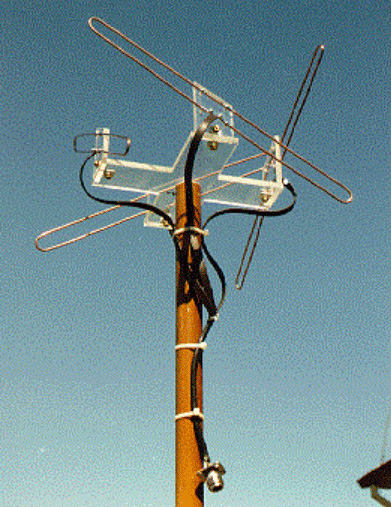
Figure 9. A Lindenblad antenna for VHF using folded dipole elements
The QFH
A newer omnidirectional design that interested me as much for its esthetics as its performance is the quadrifilar helix (QFH) antenna (Figure10), which has an almost perfect hemispherical pattern and is circularly polarized. They have been popular with space researchers and for receiving weather satellites, with many detailed plans online. It is related to directional, axial-mode helix antennas which I will describe next month. I thought it might be a bit tricky to build because of the way the helixes are supported. Recently I have seen a reasonably priced commercial version for the ham satellites.
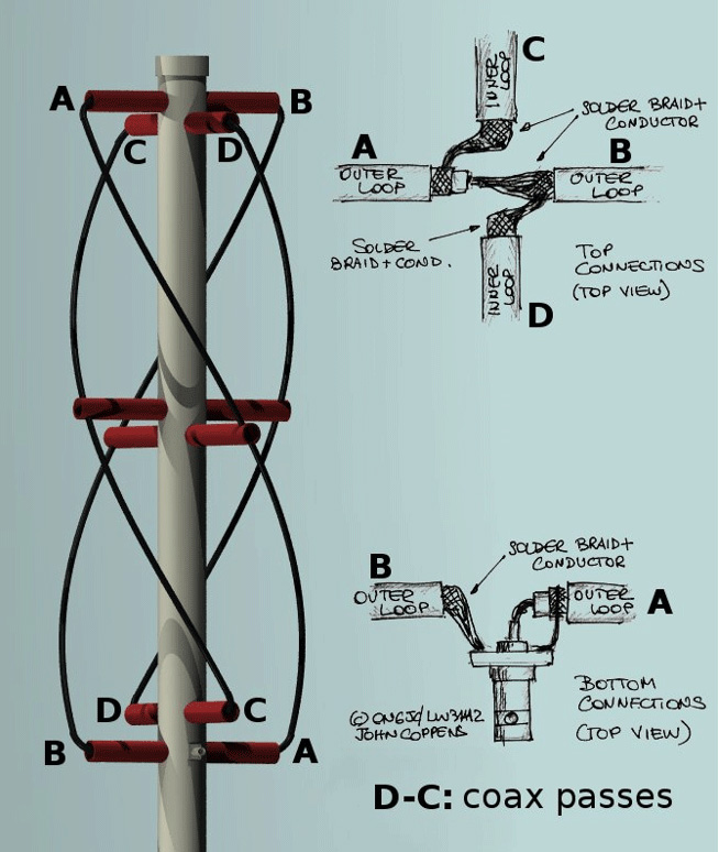
Figure 10. Construction details for a quadrifilar helix antenna
Eggbeaters
The most popular commercial “omni” for ham satellites at present is the “Eggbeater” (Figure 11). This is an improved design of the turnstile antenna, and achieves a pattern seen in Figure 12. They are manufactured by several companies but are rather expensive. Many hams use receiving preamplifiers with them (adding to the cost) and report good results on the satellites. They consist of two full wavelength loops at right angles to each other and fed 90 degrees out of phase, mounted over a horizontal reflector. With this configuration the antenna is omnidirectional and circularly polarized. Changing the feeder connection from one loop to the other loop changes the polarization between RHCP and LHCP.
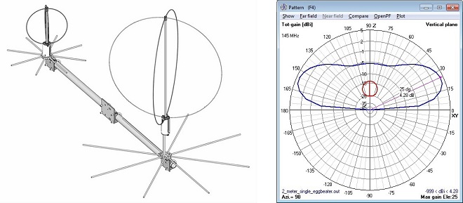
(Left)Figure 11. A pair of “Eggbeaters" for V/U satellites
(Right)Figure 12. Radiation pattern of the “Eggbeater" turnstile loop
The Moxon Turnstile
Moxon rectangles are simple two-element single-band antennas described in the 1960’s, and are widely used both on HF and as a driven element in V/U Yagi designs. They have nearly the same gain and front-to-back ratio as a full-size two-element Yagi, in a much smaller space. Online calculators have simplified the design of the basic antenna (Figure 13).
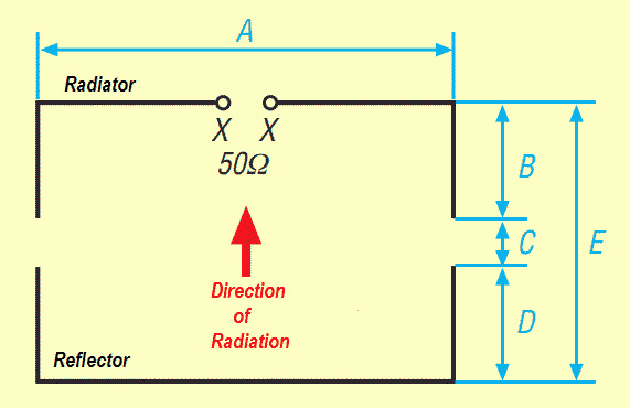
Figure 13. A calculator for the Moxon rectangle
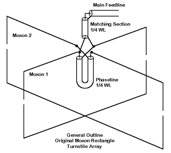
Figure 14. The Moxon Turnstile satellite antenna
The antenna expert L.B. Cebik (SK) described a Moxon Turnstile in 2001, consisting of two Moxon rectangles aimed upward and oriented at right angles to each other. The feedline connects to one rectangle’s driven element and a phasing line runs to the other one. Since each rectangle has an impedance of close to 50 Ω at resonance, the parallel impedance is 25 Ω, which is transformed to match a 50 Ω feedline.
The radiation pattern (Figure15) looked like a good complement to my directional antennas so I built one for 2 m from old TV antenna parts, which can be seen in Figure 16. After trimming the elements, I obtained broadband low VSWR centered on 146 MHz.
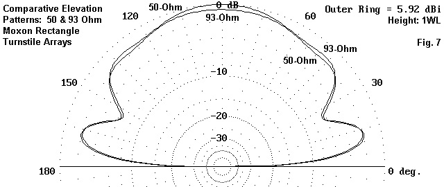
Figure 15. Radiation pattern of the Moxon Turnstile array
Alas, I had no such success building the 70 cm Moxon Turnstile! The overall size at 435 MHz is quite small, so tiny changes in any of the dimensions shown in Figure 13, or in the phasing and matching sections, affect the resonant frequency and VSWR. I found it almost impossible to adjust and eventually gave up. It appears that quite a few other hams also have had trouble building the 70 cm version. Even Mr. Cebik hinted it might be challenging, and suggested just using one Moxon rectangle.
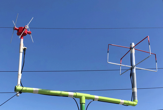
Figure 16. My omnis: (left) 70 cm Double Cross, (right) 2 m Moxon Turnstile
The Double-Cross
This is a variation on the crossed turnstile and the Lindenblad. Four dipoles are mounted as in Figure 17 (left side) to produce an oblong radiation pattern (Figure 18). The null along the X axis is filled in by adding a second pair of crossed dipoles. If the second pair is fed 90° from the first pair, the four-dipole array has a flattened hemispherical radiation pattern (Figure 19).
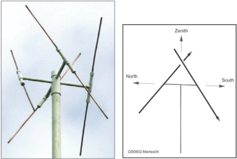
Figure 17. (left) Double Cross, (right) one crossed pair of dipoles
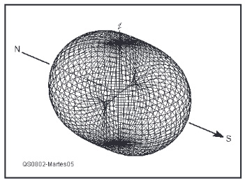
Figure 18. Radiation pattern from one pair of crossed dipoles
It was an enjoyable antenna to build, and was easy to adjust for low VSWR from 420 to 460 MHz. Mine can be seen in Figure 16. However, the radiation pattern of the Double Cross (Figure19) is not quite ideal for my antenna system, which does not need maximum gain at low elevations. The Double Cross works well enough, but a little more overhead gain for UHF would be welcome.
Figure 19. Receiving pattern of a Double Cross antenna for a weather satellite
In any case, building the high-gain directional satellite antennas was even more fun, so tune in next month!
PS - After using the Double Cross for two years, I gave the 70 cm Moxon Turnstile one more attempt recently. Cebik had published an update on the antenna, so I followed his dimensions exactly for one rectangle. After many adjustments it no longer was a neat rectangle, and the less it resembled one, the better the Smith Chart and VSWR looked. Maybe I will add another messy Moxon in the future and complete it, but for now I will finish this article and keep on using the Double Cross on 70 cm.
From Steve's Workbench backnumber
- Another SOTA antenna, and some thoughts on antenna efficiency
- The Versatile Vertical Delta Loop
- An improved portable Magnetic Loop “Magloop” Antenna
- Small wonder: The Evolution of the uSDX and other QRP transceivers
- I learned about relays by rebuilding some Workbench projects
- Cheap but effective satellite antennas – Part 2: Directional antennas
- Cheap but effective satellite antennas – Part 1: Omnidirectionals
- 18/24 MHz rotatable dipole,“Random-length”, end-fed, multiband antenna
- My shack was a jungle of cables! The solution was a remote antenna switching system.
- Remote Antenna Tuners – Part 2 – Designing, Building, and Testing a Remote Antenna Matching Unit
- Remote Antenna Tuners – Part 1 – Why Use A Remote Antenna “Tuner”