


Technical Trivia by Dr. FB
Measurement of Antenna SWR on Handheld transceivers
(Part 1)

Dr. FB
What we are worry about when we amateurs install an antenna is SWR. If you talk to a local station, who is at a communication distance that may not be satisfactory with the antenna you installed, the local station will immediately come back with a reply saying "Did you check the SWR?"
The SWR of an antenna installed outdoors can be measured by connecting an SWR meter between the radio and the antenna, as shown in Figure 1. We know that the SWR meter should be connected to the antenna as close as possible when you measure SWR. Actually, we install it to near transceiver indoors.
These days, it is very convenient to measure SWR easily without a transmitter, if you have an antenna analyzer. How do you measure the SWR of an antenna on the handheld transceiver? I will talk about how we can measure the SWR of an antenna that is installed on a handheld transceiver in this issue.
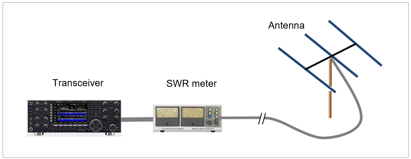
Figure 1. SWR measurement example using a pass-through power meter
1. Ratio of traveling wave power to reflected wave power
During the last 20 years, antenna analyzers have become popular among amateur radio operators. Until recently, SWR measurement had generally used a through line type power meter that can measure SWR as shown in Figure 1, and I, Dr. FB, understood that this was the only way to measure SWR. The principle of SWR measurement is the same whether it is a through a line power meter or an antenna analyzer. The ratio of the voltage of the traveling wave from the transceiver to the antenna, and the voltage of the reflected wave returning from the antenna to the transceiver, is displayed on an analog meter or digitally.
In the case of a handheld transceiver, the antenna is directly connected to the transceiver. I think that it is possible to measure by connecting as shown in Figure 2 below, but unfortunately this cannot measure the SWR of the antenna.
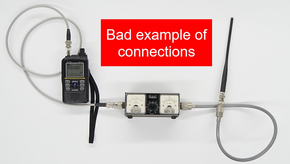
Figure 2. SWR measurement of handheld unit antenna (bad example)
2. The antenna that comes with a handheld transceiver works as a vertical quarter wave ground antenna
Many of the flexible antennas that come with a handheld transceiver work as vertical 1/4λ grounded antennas. Speaking of a 1/4λ ground antenna, the ground part plays a very important role. In the case of a handheld transceiver, as the chassis is used as a ground, and as the transceiver is used while hand-held, the ground is very unstable.
The antenna is made from a piece of wire. Signals supplied to the antenna have a very high frequency, such as 144 MHz or 430 MHz, so the antenna element itself also has components of a coil (inductance) and capacitor (capacitance). And the inside chassis and antenna element also creates capacitance. When these are combined, the antenna and the transceiver chassis can be regarded as forming an equivalent circuit as shown in Figure 3. If the RLC circuit resonates at the operating frequency, all signals output from the transceiver are supplied to the antenna, and the SWR with no returned signals becomes the ideal antenna with an SWR of 1:1.
However, the SWR measurement shown in Figure 2 shows that the capacitance between the antenna element and the transceiver is extremely low because the antenna is not directly connected to the transceiver. In other words, the value of C between the antenna element and the chassis shown in Figure 3 is close to zero, so you can expect that the resonance frequency of the equivalent circuit will resonate far above 144MHz and 430MHz.
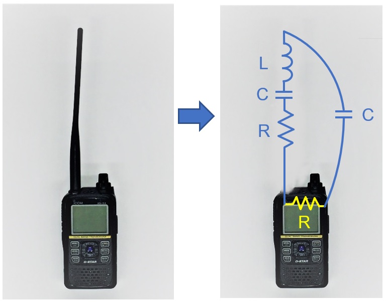
Figure 3. (Left) 1/4λ grounded antenna
(Right) Equivalent circuit of the 1/4λ grounded antenna
Then, a 1/2λ (half-wave) antenna that needs no ground is useful. Refer to the previous edition of this Technical Trivia by Dr. FB.
3. An idea of SWR measurement for an antenna of handheld transceiver
Dr. FB built a jig, as shown in Figure 5, using one ID-51 144/430MHz Dual Band transceiver. In this case, it doesn’t matter if the ID-51 works properly or is broken because we need only the ID-51 body and the inside chassis. In short, a coaxial cable is directly connected to the antenna connector. After connecting the coaxial cable directly to the antenna connector, it is important to reattach the shield plates removed during the modification, because these shield plates also work as a ground.
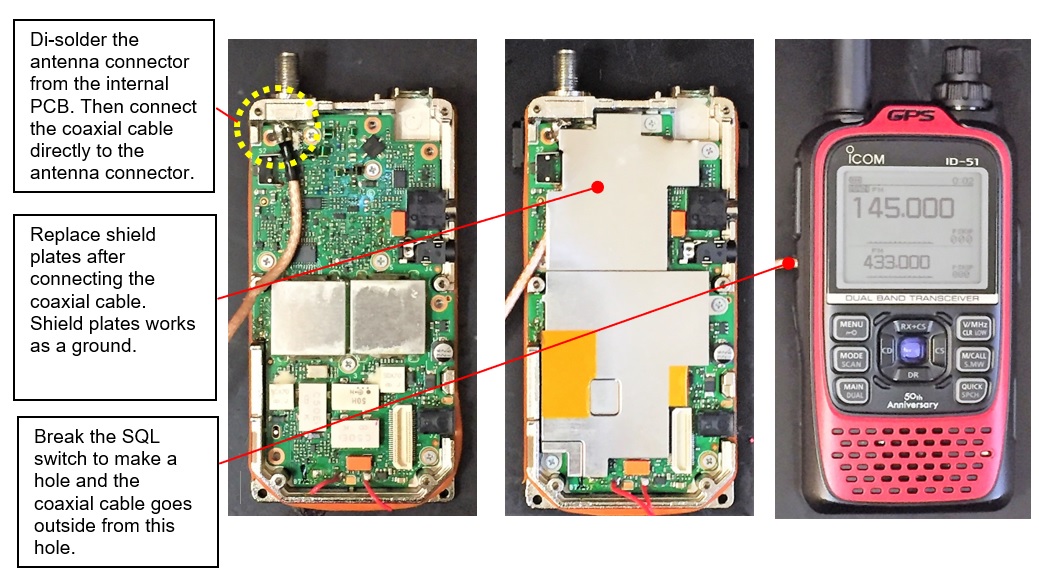
Figure 4. Example connection of a coaxial cable to an ID-51
Figure 5. Modification to attach coaxial cable to antenna connector (using ID-51)
Attach your favorite antenna to the modified ID-51 and connect the coaxial cable to the antenna analyzer to measure the antenna SWR. In actual operation, the transceiver is operated while holding in your hand, so it may not be possible to measure accurately by simply attaching the antenna to the transceiver, as shown in Figure 6. As shown in Figure 7, the SWR changes when you hold the transceiver in your hand, so it is interesting to see where with such a jig you can lower the SWR when you hold it.
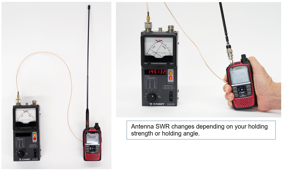
Figure 6. Measurement example Figure 7. SWR changes holding the transceiver
A 1/4λ antenna is short and easy to use, but grounding is important. However, 1/2λ antennas have the advantage of ignoring grounding, but the element is longer. Both have their pros and cons.
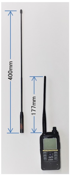
Figure 8. 400mm (commercially available V/U whip antenna) and 177mm (supplied flexible antenna)
The antenna with the 400mm element length in Figure 8 has a VHF (1/4λ) and UHF (1/2λ) configuration. The measurement results will be reported in the next issue.
FBDX
Technical Trivia by Dr. FB backnumber
- Generating “Sawtooth Waves” using a D/A conversion circuit and a counter IC
- Examining a D/A converter using a Resistor Ladder
- Electronic firefly and its circuit description
- Controlling the rotation speed of a DC motor
- Description of up-down counter using 74HC192 and 74HC4511 ICs
- Considerations when making a dual voltage power supply for operational amplifiers
- Observing filter characteristics with a white noise generator
- Is noise actually reduced in twisted pair cables?
- Experiments on divider circuits using a 74HC74
- Consideration of using a photocoupler as a voltage-variable resistor
- Distorted waveform spectrum as observed on a tinySA
- Trial making of a QFH antenna
- About the inductance of coils
- Operation of analog switches
- Small digital voltmeter, 2-wire type / 3-wire type. What is the difference?
- Constant current circuit using an Op-Amp
- Coaxial cable loss to UHF and SHF
- 2.4 GHz Wireless LAN Antenna
- Let’s use MOSFETS
- 25th Comparator
- The principle of PLL
- Examination of the MLA performance
- About the Fresnel zone of the SHF band
- Level difference under open and load ends of an SSG
- Is “Made in Japan” alive? (UHF adapter again)
- Possibility experiment of passive repeater with the Back-to-Back antenna
- Why you should make SWR measurements just below the antenna!
- How reliable is the L-type BNC?
- Is the Bird 43 accurate enough?
- Does a wire dipole antenna need a balun?
- Why we don’t use a silicon diode in a crystal radio?
- How to light the 7-segment LED
- Measurement of Antenna Performance on Handheld Transceivers (Part 3)
- Measurement of Antenna SWR on Handheld transceivers (Part 2)
- Measurement of Antenna SWR on Handheld transceivers(Part 1)
- An SWR meter
- V/UHF 3-Band Antenna Dismantling Note