


Technical Trivia by Dr. FB
Coaxial cable loss to UHF and SHF
Can wireless LAN technology be used at 2400 MHz?
Dr. FB
I disassembled and showed you the 2.4 GHz band beam antenna used for wireless LAN communication in the last issue of the Dr. FB article. I haven't checked the performance of the antenna with measuring equipment, but I feel that it can be used even in the amateur 2400 MHz band without problems. The reasons are (1) the frequency used for wireless LAN and a part of the frequency of the 2400 MHz band for amateur radio overlap. In other words, they have the similar frequency range. (2) Wireless LAN antennas are made with a fairly wide bandwidth, and it covers not only the wireless LAN frequency range but also the amateur 2400 MHz band.
2.4 GHz Wi-Fi antenna
Figure 1 shows the appearance of the 2.4 GHz wireless LAN antenna again. If you look it closely, you can see the 5D-2V cable coming out of the antenna. The length is about 70 cm. Since a Type-N connector (female) is attached to the cable end, you can see that a coaxial cable of a certain length is used.
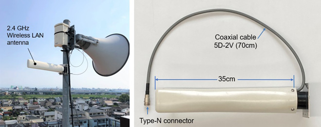
Figure 1. The 2.4 GHz wireless LAN antenna
The most popular frequency band in the UHF band for amateur radio is the 430 MHz band (430-440MHz) in Japan. It seems that the situation has changed a little since the Icom IC-9700 was announced, and the 1200 MHz activity has drastically become active. Since 1200 MHz is a very high frequency, and if we use a coaxial cable to apply RF power to an antenna, there is a lot of attenuation and it seems unusable. However, I learned that even if I use 8D-FB coaxial cable (similar to RG-8) of about 10m in length, I can make QSOs with an IC-9700 as it is.
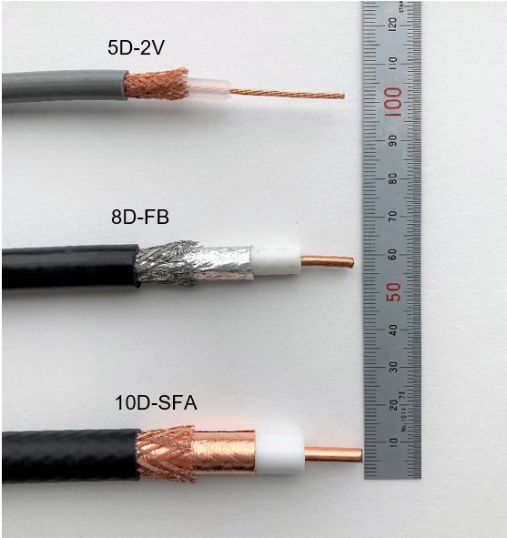
Figure 2. Major coaxial cables
But what about 2400 MHz? I'm not sure because I haven't operated it so far, but in the near future, the frequency bands such as 2400 MHz and 5600 MHz may become popular bands like the 1200 MHz band, which is an extension of the movement of 5G (5th Generation) in the world. This time, I will explore a little whether coaxial cables can be used at those frequencies, although it is only for calculation.
Attenuation amount for major coaxial cables
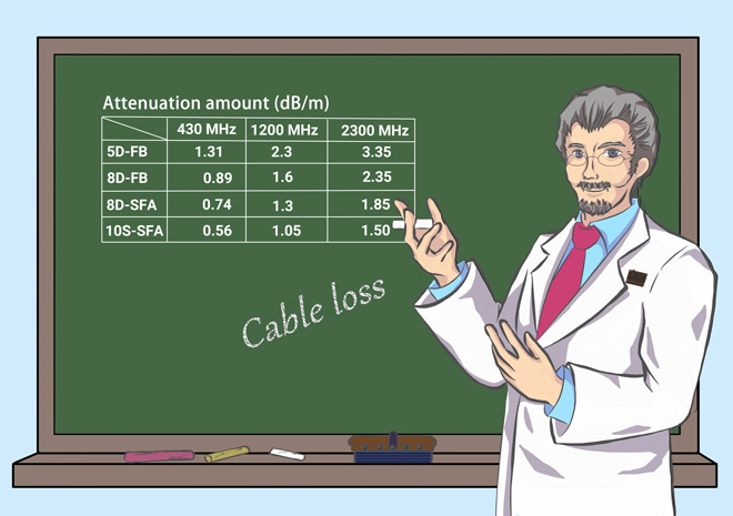
Technical data of "Attenuation amount of major coaxial cable" is posted on the homepage of Japan Amateur Radio League (JARL). Figure 3 is a portion of some of that data. Similar data is posted on the homepages of each cable manufacturer, and although the numbers are slightly different, they do not change significantly, so I will proceed using the data posted on the JARL homepage.
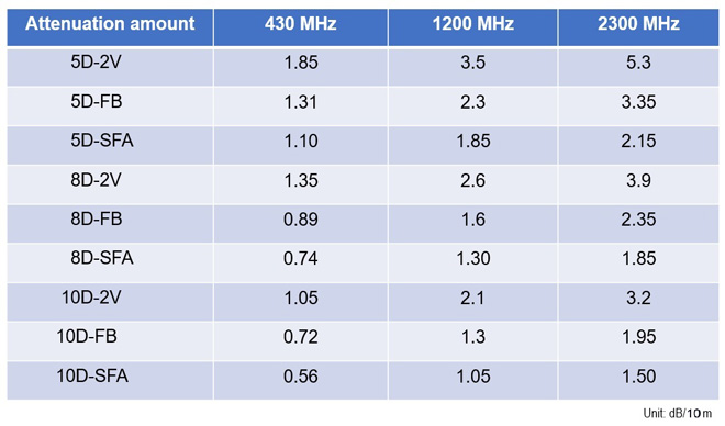
Figure 3. Attenuation amounts of major coaxial cables (Taken from the JARL website)
The data posted on JARL homepage is up to 2300 MHz. It can be inferred that there is almost no use of coaxial cable around 5600 MHz, or even if it is connected, the attenuation is extremely large and it is not usable. Since the attenuation can be made with an attenuator, it can be considered that the attenuator shown in Figure 4 is inserted in the RF feeder line between the transceiver and the antenna.
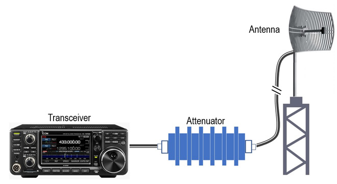
Figure 4. Coaxial cable with a large amount of attenuation is the equivalent of an attenuator.
Coaxial cable is an attenuator for SHF
I mentioned that a 5D-2V coaxial cable is attached to the 2400 MHz antenna in the beginning of this article. Since the coaxial cable has a Type-N connector attached, you can imagine that the wireless LAN system also has a coaxial cable of some length connected to the end. Let's find the loss when a 10m length of 5D-2V is connected.
From Figure 3, the attenuation of 5D-2V per 10m is 5.3 dB. Since it is attenuation, it should be described as a gain of -5.3 dB to be exact. Let's calculate how much power is input to the antenna when 2400 MHz 1 W of power is supplied from the transceiver to the antenna through the cable.

Figure 5. Loss calculation on a 10m length of 5D-2V
The logarithmic and exponential conversions are performed in Figure 5. Although it is not a familiar formula, the two have the following relationship.
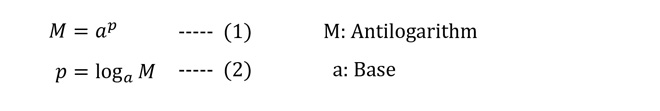
log2, log3, log10, etc. are also given to daily amateur radio activities and can be easily calculated by hand, but when it comes to the above calculation, we must use a scientific calculator, which is a useful tool.
As you can see in Figure 5, the 1 W power output from the transceiver is about 0.3 W at the end of a 10m 5D-2V cable. It is a large loss, but I think that it will be possible to recover it with the gain of the antenna.
Now, let's calculate one more thing. It costs more, but let's calculate the loss of a 10D-SFA/10m coaxial cable at 2400 MHz. Figure 3 shows only the data up to 2300 MHz, but I will proceed with this value.
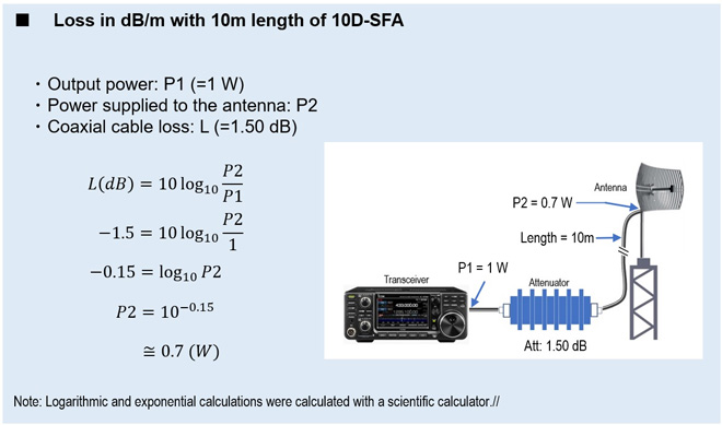
Figure 6. 10D-SFA / 10 m loss calculation
It can be seen that 0.3 W is attenuated at 1 W output and appears as 0.7 W output at the end of the coaxial cable on the antenna side. If this is a 20 m coaxial cable, the attenuation will be 2 times 1.5 dB, which is 3 dB. So, the output will be half, and is 0.5 W. Actually, I think that it will be attenuated a little more due to the loss of the connectors, but I thought that it could be used.
It is not like a new technology though
Since 2.4 GHz is also used for wireless LAN, an antenna is required for communications between two points, but the coaxial cable is not towed to the end. For example, communications are performed from a terminal unit to an access point via Wi-Fi or Bluetooth waves, and the signal is transmitted as data to just below the antenna with a wired LAN cable. There is no radio frequency signal (RF) intervening there, so there is no need to consider RF power loss. The voice and data signals of each operator's terminal unit are sent to a device installed directly underneath the antenna via the access point installed indoors and the wired LAN cable. The signal sent in each unit is D/A converted, and the 2.4 GHz RF signal is modulated with its converted signals. In this way, it is not necessary to send RF signals over a long transmission line (coaxial cable), and RF loss in the transmission line can be greatly reduced. In addition, it is good point that we do not need to purchase expensive coaxial cables.
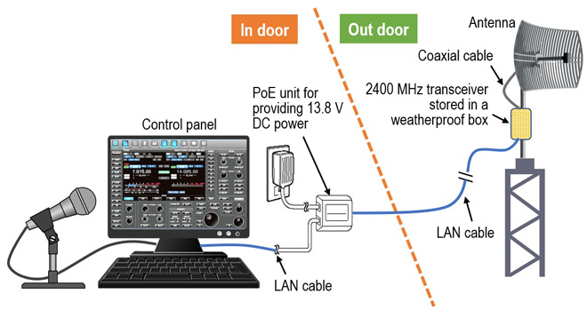
Figure 7. Image of a system without a standard length of coaxial cable
For the example shown in Figure 7, there is a good possibility that it can be realized with existing wireless LAN technology. An RF transceiver is placed directly underneath the antenna, and the signal received by the transceiver is converted to a digital signal and brought into the shack with a wired LAN cable. Transmitting is the opposite flow and it is the same as receiving. Especially in UHF and SHF, a coaxial cable causes a large RF loss, so it is a more effective method to send voice signals and data to the antenna with a LAN cable.
If you use PoE (Power over Ethernet) technology, which is also widely used in wireless LANs, you can provide DC power, such as 13.8 V DC and several amperes, to the transceiver installed directly underneath the antenna through the LAN cable without laying a DC power cable separately from the LAN cable. My dreams swell.
FBDX
<Reference>
In the part that explains the frequency of wireless LAN in the text, it is expressed as "GHz" according to the explanation of IEEE 802.11b, and in the part that explains the frequency band of amateur radio, it is expressed as "MHz" according to the band plan of JARL.
<Source of data>
JARL website https://www.jarl.org/Japanese/7_Technical/lib1/coax.htm
The data is reprinted with the permission of JARL.
Technical Trivia by Dr. FB backnumber
- Generating “Sawtooth Waves” using a D/A conversion circuit and a counter IC
- Examining a D/A converter using a Resistor Ladder
- Electronic firefly and its circuit description
- Controlling the rotation speed of a DC motor
- Description of up-down counter using 74HC192 and 74HC4511 ICs
- Considerations when making a dual voltage power supply for operational amplifiers
- Observing filter characteristics with a white noise generator
- Is noise actually reduced in twisted pair cables?
- Experiments on divider circuits using a 74HC74
- Consideration of using a photocoupler as a voltage-variable resistor
- Distorted waveform spectrum as observed on a tinySA
- Trial making of a QFH antenna
- About the inductance of coils
- Operation of analog switches
- Small digital voltmeter, 2-wire type / 3-wire type. What is the difference?
- Constant current circuit using an Op-Amp
- Coaxial cable loss to UHF and SHF
- 2.4 GHz Wireless LAN Antenna
- Let’s use MOSFETS
- 25th Comparator
- The principle of PLL
- Examination of the MLA performance
- About the Fresnel zone of the SHF band
- Level difference under open and load ends of an SSG
- Is “Made in Japan” alive? (UHF adapter again)
- Possibility experiment of passive repeater with the Back-to-Back antenna
- Why you should make SWR measurements just below the antenna!
- How reliable is the L-type BNC?
- Is the Bird 43 accurate enough?
- Does a wire dipole antenna need a balun?
- Why we don’t use a silicon diode in a crystal radio?
- How to light the 7-segment LED
- Measurement of Antenna Performance on Handheld Transceivers (Part 3)
- Measurement of Antenna SWR on Handheld transceivers (Part 2)
- Measurement of Antenna SWR on Handheld transceivers(Part 1)
- An SWR meter
- V/UHF 3-Band Antenna Dismantling Note