


Technical Trivia by Dr. FB
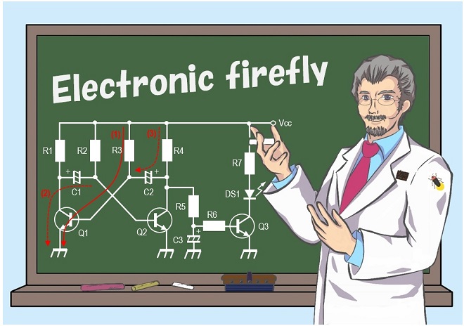
Electronic firefly and its circuit description
Introduction of three types of electronic fireflies
Dr. FB
It is not the season for fireflies, but I will be making “Electronic fireflies.” However, the main focus is not on making electronic fireflies, but on exploring how to make fireflies emit light. By assembling the circuit, I experimented with in this process, I will be able to make electronic fireflies.
If you search for "Electronic firefly" as a keyword on the Internet, you will find many more articles than you might expect. There seems to be a good reason this article was introduced. This time, I will focus on the electronic firefly, analyzing the circuit and conducting experiments.
Electronic firefly
Turning the LED ON or OFF can easily be achieved with the circuit shown in Figure 1 (below on the left). However, since this circuit only turns the LED ON and OFF, it does not make a luminescence like that of a firefly, which turns ON and OFF slowly. Something needs to be done to the circuit to make it turn ON and OFF like a firefly.
To turn ON the LEDs, it is necessary to apply the default current as specified in the LED specifications. You need to see the specification sheet for details, but a general-purpose LED will light up when a current of about 10 mA is applied.
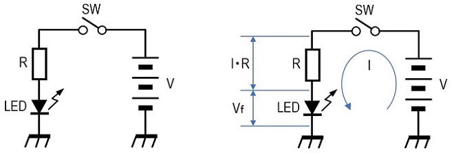
Figure 1. ON/OFF circuit for LED lighting
Figure 1 (above on the right) shows the calculation. The equation below holds for this circuit.
V = I・R + Vf
Vf is called the forward voltage of the light-emitting diode (LED), which is also listed in the specification sheet. Normally, it should not be a large error to calculate it as about 0.6 V. Resistor (R) can be obtained from the above formula with the voltage V applied to the circuit, the forward voltage Vf of LED, and 10 mA of the current flowing in the circuit.
Four ways to create electronic fireflies
The first step is to find a way to turn the LEDs ON and OFF continuously and automatically and I will explore it. I think that electronic firefly circuits posted on the Internet can be roughly classified into the following four methods. The following (1) to (3) are in the category of electronic projects made by connecting components. Of these, (2) and (3) are the circuits that come to mind immediately. In this explanation, I will conduct experiments using methods (1) through (3).
Method (4) also requires electronic components, but the main device is the Arduino, a compact microcontroller board with I/O ports, power supply, etc. Arduino was developed in Italy in 2005 and is now widely used around the world. To turn ON LEDs with this board, a little programming is required. This time I will exclude this method (4).
(1) Using an oscillation circuit consisting of two transistors (kit used in this case)
(2) How to use an unstable multivibrator circuit
(3) How to use a timer IC, NE555
(4) How to use a microcontroller board, Arduino
How to use an oscillation circuit composed of two transistors
To be honest, I had not thought of this method (1) above. I used a kit for this experiment. The kit is an oscillation circuit consisting of an NPN transistor and two PNP transistors. The term "oscillation circuit" brings to mind high frequency oscillation circuits such as 10 MHz or 20 MHz, but in essence, it is a circuit that returns part of the signal from the output stage to the input stage. A circuit diagram is printed in the instruction sheet included in the kit. The schematic diagram looks simply, but in fact, the idea of blinking LEDs with this circuit seems to be the most difficult to produce.
While searching the Internet for "Electronic firefly," I learned that an electronic firefly kit using this circuit was available from DigiHam Support (DigiHam) in Osaka Japan, and I immediately purchased it. Figure 2 shows the contents of the kit.
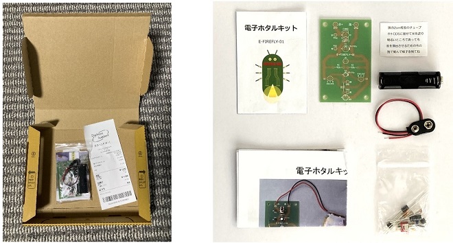
Figure 2. Electronic Firefly kit sent by Digiham Support
Making the kit is quite easy. All necessary components and a printed circuit board (PCB) are enclosed in a plastic bag. Even if you cannot read the schematic diagram, you can insert the components while looking at the picture of the finished product printed on the instruction sheet, and the kit can be completed in 30 minutes. Looking at the schematic diagram, this would allow you to collect all components and make it yourself. However, considering the time and effort required to collect the components and the complete PCB is also included in the kit, the kit is likely to be cheaper.
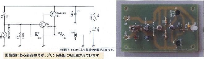
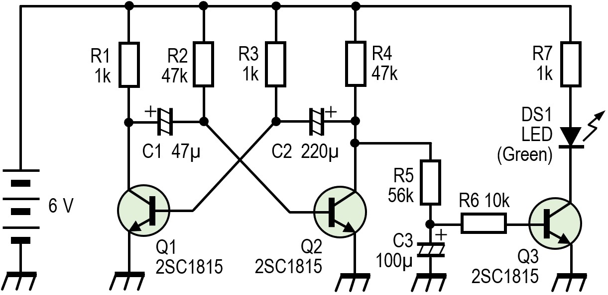
Figure 3. Electronic firefly schematic diagram and finished board as shown in the instruction sheet
Figure 4 shows the "Electronic firefly" actually completed by inserting the components into the PCB. The operation can be checked by either darkening the area or covering the CdS of the installed components with a black tube.
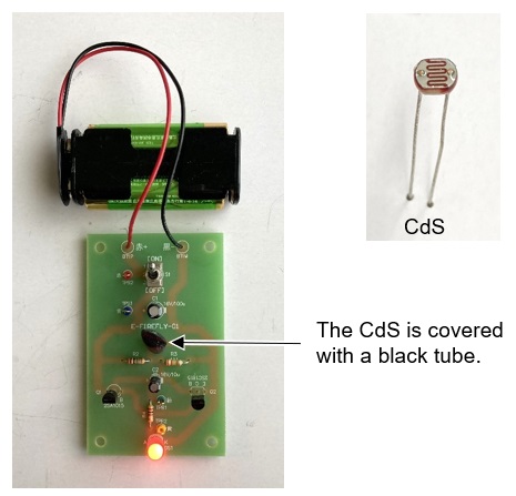
Figure 4. Electronic firefly in the completed kit (CdS covered with a black tube)
・Flashing Principle
Look at the schematic diagram in Figure 3 shown above. Q2 is an NPN transistor. When current flows to the base, Q2 turns ON and current flows from the collector to the emitter. This is a basic operation of transistors. The key component involved in turning Q2 ON and OFF is CdS (R1). CdS has a low resistance value at both ends of the lead wire when its surface is illuminated, and an extremely high resistance value when it is dark and not illuminated. This characteristic is used to make the LED of the electronic firefly blink when the surroundings are dark.
For reference, when I measured the resistance of the CdS included in the kit and found that it dropped to 100 Ω or less in sunlight. Conversely, in the dark, it reached several MΩ.
When the ambient light is bright, R1 has a low resistance value and the base voltage of Q2 is very low relative to GND, so no current flows between the Q2 base and emitter, and Q2 is OFF. In other words, no current flows from the collector to the emitter. Q1 is also OFF because no current flows from the emitter to the base. Therefore, no current flows to LED (DS1) and the LED does not light up.
When the ambience becomes dark, the resistance of CdS becomes extremely high and current flows through R2 to the base of Q2, Q2 turns ON and current flows from the collector to the emitter. Then, current from the emitter of Q1 to the base and Q1 also turns ON. Therefore, current also flows from the emitter of Q1 to the collector, and this current flows through R4 and DS1, causing the LED to emit light.
At the same time, the current that flows from the emitter of Q1 to the collector also flows into C2, charging C2, and as the voltage at both ends of C2 increases due to the charging of C2, the potential of the base of Q2 decreases, and no current flows into the base of Q2. In other words, Q1 and Q2 are turned OFF and the LED turns OFF.
When Q1 and Q2 are turned OFF, C2 remains charged, and this charged charge is gradually discharged through the LEDs. When discharged, Q1 and Q2 return to the state they were in when the power was first turned ON, and the LED turns ON again. This repetition causes the LED to blink.
How to use the unstable multivibrator
An unstable multivibrator is an electrical circuit whose output pin cycles between Low (L) and High (H) states. It is used to create clock signals. Here, the unstable multivibrator is made with two transistors to make an LED blink.
Use this unstable multivibrator to create a blinking firefly. To the output of that flashing light, I added a transistor and an integrating circuit to create a state in which the light turns ON slowly and goes OFF slowly. The experimental circuit, shown in Figure 5, consists of R5, C3, R6, and Q3.
・Circuit description of the unstable multivibrator
Figure 6 shows a typical schematic diagram of an unstable multivibrator. If there is a circuit in which two transistors are depicted facing each other in the circuit, then it is definitely a circuit that is called a multivibrator.

Figure 6. Principle of unstable multivibrator
The multi-vibrator has the following three modes of operation.
1. Bistable mode
2. Monostable mode
3. Unstable mode
The device used for this electronic firefly is called an unstable multivibrator. This circuit outputs L and H from point A or B when power is connected, and the signal continues to output until power is disconnected. The principle of its operation is briefly explained below.
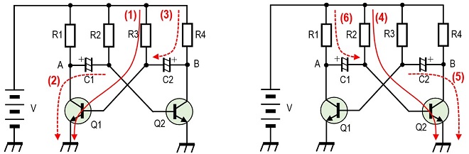
Figure 7. Current flow representing the principle of operation of the unstable multivibrator
When the power supply V is connected to the circuit, a current of either (1) or (4) flows. In this explanation, the flow in (1) occurs first, and the explanation begins with Q1 being turned ON.
1. When power is connected, current (1) flows to the base of Q1 through R3, and Q1 is turned ON.
2. Since Q1 is ON, point A becomes the GND level, and the charge in C1 is discharged by the flow of (2).
3. Therefore, no current flows into the base of Q2, and Q2 is turned OFF.
4. When Q2 is in the OFF state, point B is H.
5. Current (3) flows into C2 through R4 and charging starts.
6. When C1 finishes discharging, current (4) flows to the base of Q2 through R2.
7. Then, Q2 is turned ON.
8. While Q2 is ON, C2 is discharged and Q1 is turned OFF.
9. Since Q1 is OFF, charging of C1 begins.
10. When the charging of C1 is completed, the current (1) again flows into the base of Q1 through R3.
11. Again, Q1 turns ON. These cycles are repeated.
With the repetition of the above operation 1 to 11, Q1 and Q2 are turned ON and OFF repeatedly, and H and L are output continuously at collector points A and B of Q1 and Q2. In this electronic firefly, since the light needs to be turned ON slowly, the output from point B is taken out by R5 and C3 as shown in Figure 5, and the transient phenomenon of the voltage is used to turn the light ON and OFF slowly.
How to use a Timer IC NE555
The first circuit that comes to mind for a circuit that performs the flickering LED operation is probably the use of this NE555 timer IC.
The NE555 is an 8-pin IC commonly referred to as a timer IC. In addition to its use as a timer, it is sometimes used to generate pulses or as an oscillator. This IC has the following three modes of operation. The NE555 operates as an oscillator circuit in one of the three modes to make the LEDs blink.
Since the main purpose of this project is to create electronic fireflies, I added the integrating circuit used in Figure 5 to the output of the NE555 and drove the LEDs with a transistor in order to achieve natural light emission like that of fireflies, rather than just blinking LEDs. Figure 8 shows the circuit and the experimental board. The circuit consisting of R4, C3, and R5 in Figure 8 is an integrating circuit
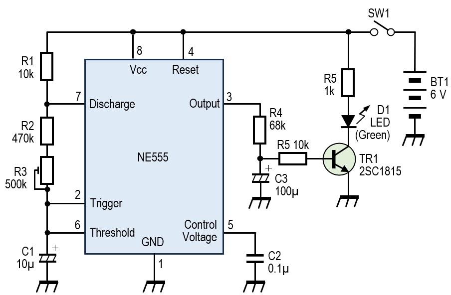
Figure 8. Electronic firefly circuit using NE555 timer IC and experimental board
・Circuit description
When the NE555 is used as an oscillator, the frequency and duty cycle can be determined in the manner shown in Figure 9.
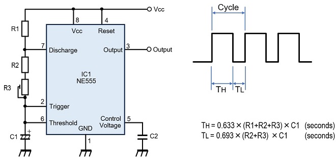
Figure 9. How to find the basic frequency and duty cycle
In the experimental circuit shown in Figure 8, the constants of each component that determine the output frequency are shown below.
R1 = 10 kΩ
R2 + R3 = 470 kΩ~970 kΩ
C1 = 10 µF
Based on these constants, TH and TL can be obtained as follows.
TH = 3.0~6.2 seconds
TL = 3.2~6.7 seconds
When the output pin (pin 3) of NE555 is H, the voltage at the junction point of R4 and C3 gradually rises in the integrating circuit composed of R4 and C3. The LED will light up slowly accordingly. (Figure 8)
By adjusting R3 shown in Figure 8, the time for the LED to turn ON or OFF can be adjusted. Also, by changing the capacitance of C3, the time from OFF to ON and ON to OFF can be adjusted.
Illumination reference
Illumination samples are uploaded in a server, so you can click the photo below to see the illuminations. The illuminations are from the LED, are from the left a circuit using the NE555, the center is a multivibrator circuit, and the far right is a commercially available kit that emits light.
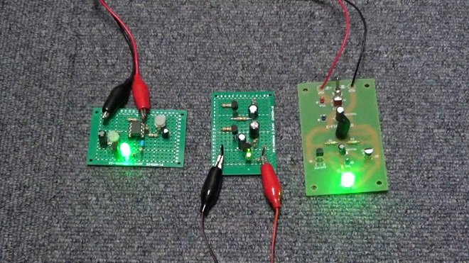
Figure 10. Illumination samples for each circuit (Click to see illuminations.)
FBDX
Technical Trivia by Dr. FB backnumber
- Generating “Sawtooth Waves” using a D/A conversion circuit and a counter IC
- Examining a D/A converter using a Resistor Ladder
- Electronic firefly and its circuit description
- Controlling the rotation speed of a DC motor
- Description of up-down counter using 74HC192 and 74HC4511 ICs
- Considerations when making a dual voltage power supply for operational amplifiers
- Observing filter characteristics with a white noise generator
- Is noise actually reduced in twisted pair cables?
- Experiments on divider circuits using a 74HC74
- Consideration of using a photocoupler as a voltage-variable resistor
- Distorted waveform spectrum as observed on a tinySA
- Trial making of a QFH antenna
- About the inductance of coils
- Operation of analog switches
- Small digital voltmeter, 2-wire type / 3-wire type. What is the difference?
- Constant current circuit using an Op-Amp
- Coaxial cable loss to UHF and SHF
- 2.4 GHz Wireless LAN Antenna
- Let’s use MOSFETS
- 25th Comparator
- The principle of PLL
- Examination of the MLA performance
- About the Fresnel zone of the SHF band
- Level difference under open and load ends of an SSG
- Is “Made in Japan” alive? (UHF adapter again)
- Possibility experiment of passive repeater with the Back-to-Back antenna
- Why you should make SWR measurements just below the antenna!
- How reliable is the L-type BNC?
- Is the Bird 43 accurate enough?
- Does a wire dipole antenna need a balun?
- Why we don’t use a silicon diode in a crystal radio?
- How to light the 7-segment LED
- Measurement of Antenna Performance on Handheld Transceivers (Part 3)
- Measurement of Antenna SWR on Handheld transceivers (Part 2)
- Measurement of Antenna SWR on Handheld transceivers(Part 1)
- An SWR meter
- V/UHF 3-Band Antenna Dismantling Note