


Technical Trivia by Dr. FB
Trial making of a QFH antenna
Dr. FB
Earthquake forecast by radio waves
It was a long time ago, but I have read in some magazines that various sky luminous phenomena were reported at the time of the "1995 Hyogo-ken Nanbu Earthquake", commonly known as the "Great Hanshin-Awaji Earthquake," which occurred on January 17, 1995. I read in a magazine that there were reports of various luminous phenomena in the sky before and after the earthquake, such as the sky glowing brightly for a moment or the sky turning pale. Many researchers believe that this phenomenon of the sky glowing is caused by something acting on the electromagnetic waves or the ionosphere before or after an earthquake. Among others, Yoshio Kushida, who is famous for discovering comets and asteroids, is also challenging the research of earthquake prediction using radio waves at the Yatsugatake South Base Observatory in Hokuto City, Yamanashi Prefecture. (Figure 1)
When I visited the observatory that Mr. Kushida was the representative of, I saw Yagi antennas for FM broadcasting reception pointing their beams to the sky all over the premises to receive FM broadcasts. As the FM broadcast waves are VHF (76.1~94.9 MHz) and it cannot be received far, several hundred kilometers, under normal circumstances unless there is an abnormal propagation. Mr. Kushida tuned the frequency of his tuner to the frequency of a station that cannot normally be received, and observed the state of reception 24 hours a day. The fact that he is able to receive frequencies that cannot be received normally could be due to changes in the ionosphere caused by an increase in the SSN (Sunspot Number), but it could also be due to changes in the ionosphere caused by an earthquake precursor that leads to abnormal propagation.

Figure 1. Books on earthquake prediction written by Mr. Kushida
A Yagi antenna pointed to the sky
In addition to researching earthquake forecasting, I was also interested in Yagi antennas pointed to the sky, so I interviewed a friend who tried to build a QFH antenna for reception of FM broadcasting. The QFH antenna, which stands for Quadrifilar Helical antenna, was originally developed for receiving NOAA weather satellites.
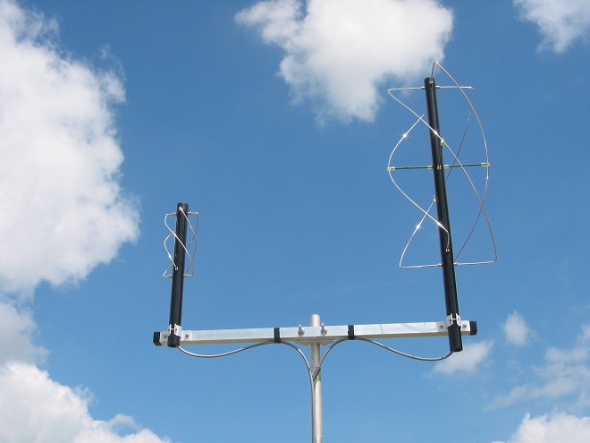
Figure 2. Nagara QFH243 (144/430 MHz band QFH antenna)

Figure 3. Earthquake prediction system at Yatsugatake South Base Observatory
The directional characteristics of a general QFH antenna are shown in Figure 4 according to the information on the website of Nagara Denshi Kogyo Co., Ltd. The horizontal beam viewed from above has a circular shape of the omni-directional beam similar to a whip antenna, and the vertical beam viewed from the side has a semicircular sphere shape with side lobes near the bottom. The antenna is perfect for receiving radio waves come from high elevation angles, such as those from meteorological satellites and GPS, or waves reflected by the ionosphere.
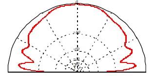
Figure 4. Beam pattern of a QFH antenna
Performance of the QFH antenna for FM broadcasting
The completed antenna in this article is not designed for amateur radio use, so it cannot be tested for actual transmission, but I used a measuring instrument to simply measure the SWR and impedance against the frequency range.
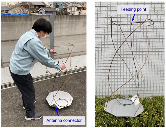
Figure 5. The completed QFH antenna for FM broadcast reception
Figures 6 and 7 show the SWR characteristics of the antenna as a function of frequency. In Figure 6, you can see that the minimum SWR is approximately 1.5 at 87.52 MHz, and the SWR exceeds 3 when the frequency is near the upper limit of the FM broadcasting band. But considering that it is for reception only, I think it is well done that the SWR is within 3.5 in the 76.1~94.9 MHz portion of the FM broadcasting band.
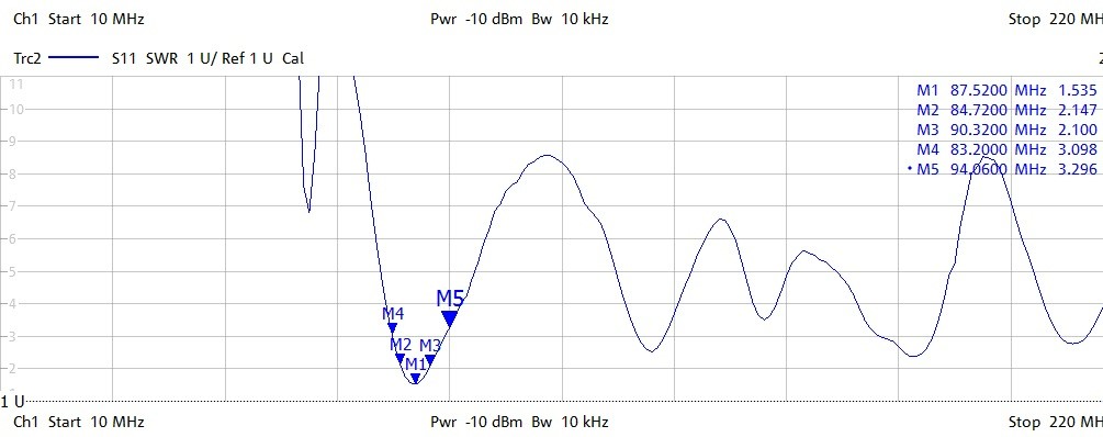
Figure 6. SWR characteristics versus frequency
The characteristics of the antenna were very critical. The SWR varied depending on the location of the coaxial cable, which was matched from the antenna's feeding point. This is why there is some difference in the graphs shown in Figures 6 and 7. The picture on the right side of Figure 7 shows the SWR and impedance measured with an antenna analyzer familiar to amateurs, and it can be seen that at 82.333 MHz, the impedance Z = R+jX has a resistance of R=50 Ω and a reactance of X=8 Ω, with the reactance as close to 0 Ω as possible.
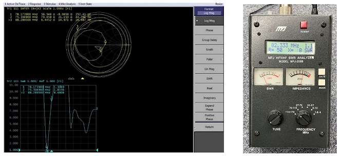
Figure 7. Change in SWR and impedance
Structure and the QFH antenna for FM broadcasting
The length and diameter of each element is calculated automatically at the following site, and the antenna should be fine tuned after building it.
http://www.jcoppens.com/ant/qfh/calc.en.php
The antenna elements are made of 6 mm diameter copper pipes. The thickness is 1 mm. It is not that hard to bend and is rather easy to make the shape you want. The height of the antenna is over 1 meter, and its diameter is over 50 centimeters, so even though it is made of copper pipe, it is not strong enough to stand on its own. A cardboard core was used to support the copper pipe and was taken out after the antenna was completed, as shown in Figure 8.

Figure 8. Assembling the cardboard as the core of the antenna and making it stand on its own.

Figure 9. Structure of each part
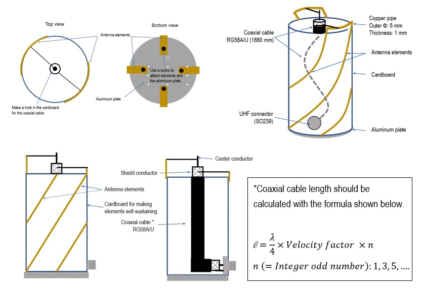
Figure 10. Structure of the QFH antenna
Reception test after completion
I made a rod antenna and connected it to the IC-705 first for the first test. Then, I replaced the rod antenna with the QFH antenna, and tested the reception of FM broadcast stations for a second test. As shown in the upper part of Figure 11, there was no difference in the S-meter level between the two antennas when they were set vertically. When both antennas were laid down, as shown in the lower part of the figures, a large directivity was observed in the rod antenna. When the tip of the rod antenna was pointed in the direction of the broadcasting station, the S-meter indication was significantly reduced, whereas the QFH antenna was able to receive signals almost as strongly in any direction. The directionality is as theoretically correct.
Although the QFH antenna has not been used in the Yatsugatake South Base Observatory for observing signs of earthquakes by radio waves, I believe that it is effective for this observation because its directivity points toward the sky.
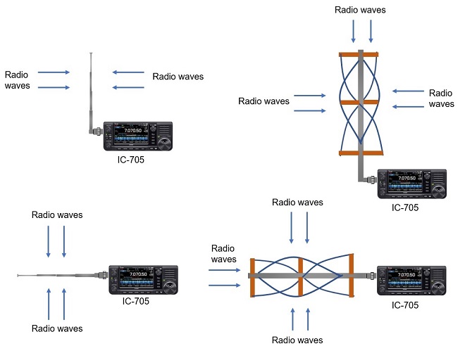
Figure 11. Differences in directivity between the rod antenna and QFH antenna
FB DX
Technical Trivia by Dr. FB backnumber
- Generating “Sawtooth Waves” using a D/A conversion circuit and a counter IC
- Examining a D/A converter using a Resistor Ladder
- Electronic firefly and its circuit description
- Controlling the rotation speed of a DC motor
- Description of up-down counter using 74HC192 and 74HC4511 ICs
- Considerations when making a dual voltage power supply for operational amplifiers
- Observing filter characteristics with a white noise generator
- Is noise actually reduced in twisted pair cables?
- Experiments on divider circuits using a 74HC74
- Consideration of using a photocoupler as a voltage-variable resistor
- Distorted waveform spectrum as observed on a tinySA
- Trial making of a QFH antenna
- About the inductance of coils
- Operation of analog switches
- Small digital voltmeter, 2-wire type / 3-wire type. What is the difference?
- Constant current circuit using an Op-Amp
- Coaxial cable loss to UHF and SHF
- 2.4 GHz Wireless LAN Antenna
- Let’s use MOSFETS
- 25th Comparator
- The principle of PLL
- Examination of the MLA performance
- About the Fresnel zone of the SHF band
- Level difference under open and load ends of an SSG
- Is “Made in Japan” alive? (UHF adapter again)
- Possibility experiment of passive repeater with the Back-to-Back antenna
- Why you should make SWR measurements just below the antenna!
- How reliable is the L-type BNC?
- Is the Bird 43 accurate enough?
- Does a wire dipole antenna need a balun?
- Why we don’t use a silicon diode in a crystal radio?
- How to light the 7-segment LED
- Measurement of Antenna Performance on Handheld Transceivers (Part 3)
- Measurement of Antenna SWR on Handheld transceivers (Part 2)
- Measurement of Antenna SWR on Handheld transceivers(Part 1)
- An SWR meter
- V/UHF 3-Band Antenna Dismantling Note