


Technical Trivia by Dr. FB
Why we don’t use a silicon diode in a crystal radio?

Dr. FB
About 50 years ago, I saw a radio called a "Crystal Radio." It was a simple radio in which a coil, a variable capacitor, and two or three other parts were placed on a wooden board, and an earphone was connected to it. I was so impressed to listen to broadcasts from the earphone of a radio with no batteries.
It is called a germanium radio in other countries, because it uses a germanium diode to detect the audio signal. Although the performance of semiconductors has improved significantly these days, no one calls it a "Silicon Radio." Since LEDs (light emitting diodes) are also a type of diode, I wondered if they could be used as a detection diode for the crystal radio, so I conducted an experiment. In this article, I will talk about that crystal radio (germanium radio).
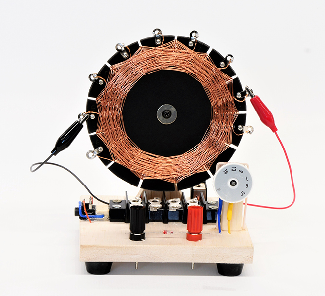
Figure 1. Crystal radio
1. Why is an LED not used for the crystal radio?
I will write from the conclusion first. The crystal radio could not receive radio broadcasts signals with both LED and silicon switching diodes. It's a very rough explanation, but I could receive radio broadcasts and heard a beautiful sound using a germanium diode. Even if a high-performance silicon diode with a high-speed switching time was used, it could receive broadcast radio signals, but no sound was produced.
The crystal radio is the simplest radio receiver. No external power is necessary, but it produces sound. The key part of the crystal radio is the diode that detects the audio signal. This time, I collected various kinds of diodes for this audio detection, and conducted experiments to determine which diode can detect audio, and which diode cannot.
2. Difference between the germanium diode and silicon diode
Let me talk a little about the difference between germanium and silicon diodes. A major factor that distinguishes whether or not a radio broadcast can be received is the characteristics of the diode. To enable a current to flow in a diode, apply a positive (+) voltage to the anode and a negative (-) voltage to the cathode. When the voltage is gradually increased from 0 V, a current begins to flow in the germanium diode at approximately 0.2 V. But the silicon diode needs 0.7 V or higher for the current to flow. In other words, you can hear the sound when the current flows in a diode.
The voltage at which the current begins to flow is called the forward voltage. It is written as VF in the manufacturer's data sheet. The germanium diode has a VF of about 0.2 V, and the silicon diode has a VF of about 0.7 V. The difference of 0.5 V separates whether the radio outputs sound or not. A VF = 0.2 V of a germanium diode is an extremely low value, which is a great feature of germanium diodes.
3. Let’s try to receive broadcasts signals with variety of diodes!
Speaking of the crystal radio, the 1N60 is a popular diode used for audio detection, but the original 1N60 has been discontinued, and its equivalent products, the 1N60P and 1N60H are on the market. In this article, I tried to confirm how the difference in VF (Forward voltage) of each diode affects the reception of AM broadcasting by receiving actual audio signals.
I made a crystal radio for the experiment. Figure 1. at the beginning is the complete crystal radio, and Figure 2. is its schematic diagram. The diode for detection has mounting terminals for easy replacement. Figure 3. is a close-up photograph of the mounting part of the diode.
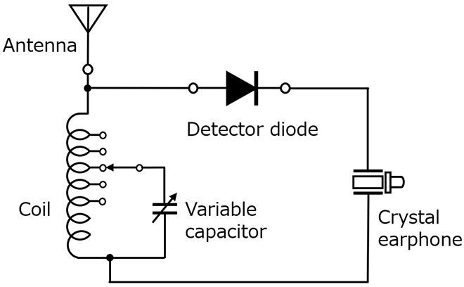
Figure 2. Crystal radio schematic diagram
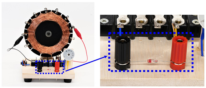
Figure 3. Wave detector diode
Look at the picture of the crystal radio coil in Figure 1. or 3. You can see that there are many taps around the coil. Originally, the resonance frequency (f0) of the parallel resonance circuit of the coil and the capacitor can be calculated by the formula shown below.

The capacitance of the variable capacitor was stated as 220 pF in the package at the time of purchase. When trying to receive signals at 666 kHz and 828 kHz broadcasts of NHK Radio Broadcasts, the coil can be calculated to be approximately 200 µH. However, I didn't have a way to measure the inductance of the coil, so I decided to find where the best inductance was by using the cut and try method. Then, I used 15 meters of 0.3 mm polyurethane coated wire to make a 90 turn figured spider-web coil. Since the tap of the coil was taken out every 10 turns, several terminals are selectable around the coil.
4. Readability under varaiety of diode
A digital multimeter I have can measure the VF of diodes. The VF of each diode was measured, and the values are shown in Figure 4. below.
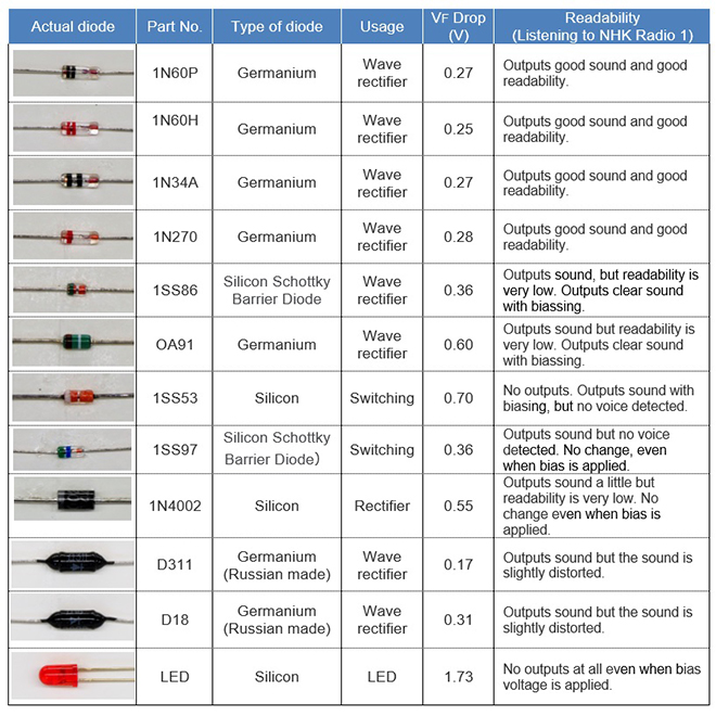
Figure 4. Measurements results
5. Verification of measurements results
The first place I measured was located on a straight line about 9 km from the NHK Radio 1 antenna (100 kW). I can say that the area 9 km away from the transmitting station is a strong electric field area. Therefore, I used a 3 meter length of wire for the crystal radio as an antenna.
As a result, there were several types of diodes that could detect audio. 1N60P (1N60 equivalent), 1N60H (1N60 equivalent), 1N34A, 1N270, and two Russian diodes. I thought that any germanium diode can detect the audio signals, but some germanium diodes could not. NHK Radio 2 broadcasts at 300 kW. Because it is a huge amount of RF power, I thought they could sound from the earphone, but the result was still the same.
Depending on the receiving area, the VF of the diode that was able to clearly detect, was one with a 0.2 V level at the experimental location, and a diode with a VF higher than that could not be heard, even if I listened carefully.
In conclusion, it can be seen that which one can and cannot be detected is due to the VF (forward voltage) of the diode.
I had one strange feeling. The VF of the D311 Russian diode is 0.17 V, which is by far the lowest. When this diode was used for detection, the received sound was louder than when an 1N60P was used. However, the sound from the earphone was not smooth. It sounded rather distorted.
6. How does output from the earphone change when apply biasing?
The VF of the diode that could not be detected is approximately 0.3 V or higher, as seen in Figure 4. As shown in Figure 5, there is a method of connecting a 1 MΩ resistor in series with a 1.5 V or 3 V battery and biasing this diode. By doing this, the diode is turned ON first, and the apparent VF is lowered so that a weak signal can pass through the diode.
As a result, you can hear the signal that you could not hear before, and realize the effect of the bias method. On the other hand, the sound that was clearly heard until now was distorted by biasing the diode.
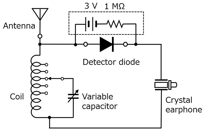
Figure 5. Bias circuit
7. Can an LED be used as a detection diode under the 100 kW station?
I was interested in whether an LED could be used as a detection diode directly under the 100 kW transmitting antenna of NHK Radio 1, or if it would light up, so I went to where the antenna is located and conducted an experiment. The result was no good. I didn't hear anything. The LED did not light up either. It was the same even if I applied a bias.
I thought that I could see some changes if I received signals from NHK Radio 2 (300 kW), which was several hundred meters away from the NHK Radio 1 antenna, and I went there. However, even 300 kW was no good. Instead, the sound detected by the germanium diode was loud enough to be heard, just by bringing the earphone close to the ear.
A germanium diode is suitable for detection because not only the VF is low, but also its rising characteristics are gentle. It can be said that the 1N60 is suitable for converting the amplitude of AM into an audio voltage.

(Left) NHK Radio 1 antenna 666 kHz/100 kW
(Right) NHK Radio 2 antenna 828 kHz/300 kW
Figure 6. NHK Radio antennas
For reference, when I told this to an American friend of mine, he told me that what is called “Crystal Radio” in the US is called "Germanium Radio" in Japan.
FBDX
Technical Trivia by Dr. FB backnumber
- Generating “Sawtooth Waves” using a D/A conversion circuit and a counter IC
- Examining a D/A converter using a Resistor Ladder
- Electronic firefly and its circuit description
- Controlling the rotation speed of a DC motor
- Description of up-down counter using 74HC192 and 74HC4511 ICs
- Considerations when making a dual voltage power supply for operational amplifiers
- Observing filter characteristics with a white noise generator
- Is noise actually reduced in twisted pair cables?
- Experiments on divider circuits using a 74HC74
- Consideration of using a photocoupler as a voltage-variable resistor
- Distorted waveform spectrum as observed on a tinySA
- Trial making of a QFH antenna
- About the inductance of coils
- Operation of analog switches
- Small digital voltmeter, 2-wire type / 3-wire type. What is the difference?
- Constant current circuit using an Op-Amp
- Coaxial cable loss to UHF and SHF
- 2.4 GHz Wireless LAN Antenna
- Let’s use MOSFETS
- 25th Comparator
- The principle of PLL
- Examination of the MLA performance
- About the Fresnel zone of the SHF band
- Level difference under open and load ends of an SSG
- Is “Made in Japan” alive? (UHF adapter again)
- Possibility experiment of passive repeater with the Back-to-Back antenna
- Why you should make SWR measurements just below the antenna!
- How reliable is the L-type BNC?
- Is the Bird 43 accurate enough?
- Does a wire dipole antenna need a balun?
- Why we don’t use a silicon diode in a crystal radio?
- How to light the 7-segment LED
- Measurement of Antenna Performance on Handheld Transceivers (Part 3)
- Measurement of Antenna SWR on Handheld transceivers (Part 2)
- Measurement of Antenna SWR on Handheld transceivers(Part 1)
- An SWR meter
- V/UHF 3-Band Antenna Dismantling Note