


Technical Trivia by Dr. FB
How to light the 7-segment LED

Dr. FB
Radios and measuring instruments that we usually use for amateur radio always have some kind of digital display installed on the front panel. The most common digital display used is the liquid crystal display (LCD) shown in Figure 1 (left), and the other is the 7-segment LED display shown in Figure 1 (right). Recently, a dot-matrix display, like a computer monitor, has become popular.
In this article, we will perform a simple experiment of lighting the 7-segment LED display, and the intended characters, with simple parts. Some unfamiliar words, such as Binary-Coded Decimal (BCD) appear, but I think most of you are familiar with digital, so you know them.
1. Digital display installed on the panel
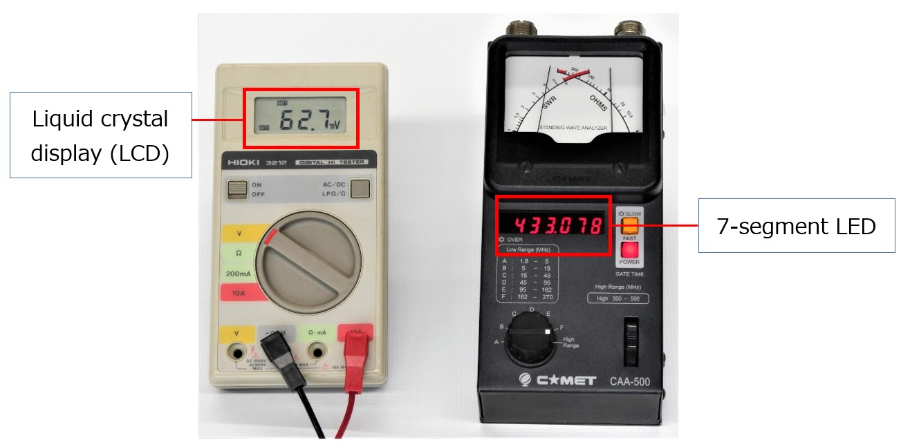
Figure1. Digital display installed on the panel
2. About an LED
The 7-segment LED display has 8 light-emitting diodes, including the decimal point, installed in its package. The principle of a 7-segment LED is simple. Once you understand the principle of one LED, you can light a desired number with some parts. Let's take a closer look at the LED.
There are two specifications that LED light emission depends on. One is forward voltage (VF) and the other is forward current (IF). For an accurate circuit design, it is necessary to look at the manufacturer's data sheet, but for the time being, let's talk about the point of turning ON (light emission).
Generally, when trying to emit light from an LED, a voltage higher than VF is required as the voltage applied to the anode and cathode. VF should be approximately 2 V for general LEDs. The other is the magnitude of the current IF (forward current) flowing through the LED. The brightness changes, depending on the magnitude of IF. Normally, it is about 10 to 20 mA, and Dr. FB usually decides on 10 mA because it saves energy. It is convenient to remember VF = 2 V and IF = 10 mA. And it is easy to calculate the current flow using Ohm’s law. Let's find the resistance of RS that limits the current flowing through the LED.
When the power supply voltage is 6 V, and the current flowing through the LED is 10 mA, RS can be calculated using the formula below. In the calculation, RS = 400 Ω, but 400 Ω resister is not available in my parts box, so I use a 560 Ω resister, which I have.
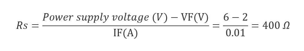
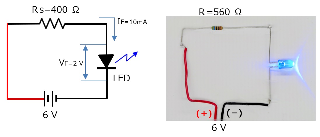
Figure 2. Experiment of lighting an LED
3. About the 7-segment LED
The 7-segment LED package contains eight individual LEDs. Take a look at Figure 3. There are two types of LEDs: a common cathode connection in which the cathodes are commonly connected, and a common anode connection in which the anodes are commonly connected, as shown in Figure 3. below. Use it according to the type of circuit you are using. This time, we will use the common cathode LED. Since it is a cathode common connection, connect all the cathode leads to (-) and apply a (+) voltage to each anode lead, and the LED of each segment will light up. Of course, you need to consider the IF shown in the previous calculations.
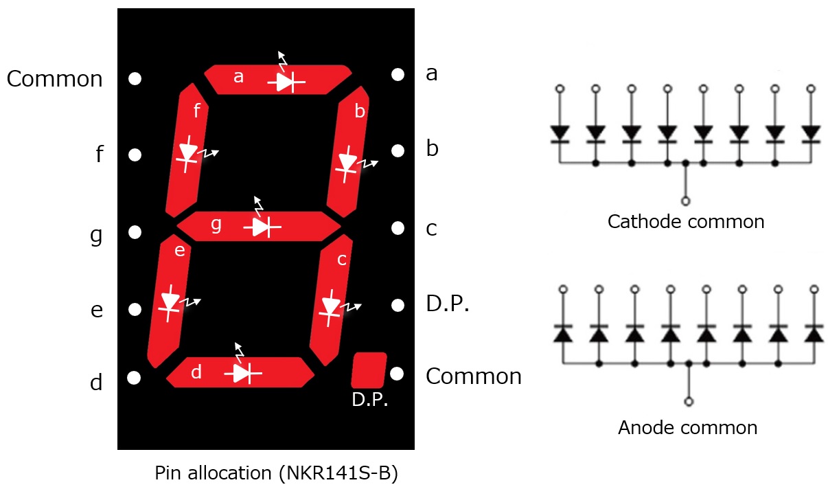
Figure 3. Illustration of the 7-segment LED
4. How to light the cathode common LED
Figure 4. shows the circuit diagram to light each segment. This time, we select 12 V DC as a power supply voltage. A resistance of 1 kΩ is required to allow a current of 10 mA to flow through each diode. Figure 5. shows the circuit that is built into a universal board according to the circuit in Figure 4. below.
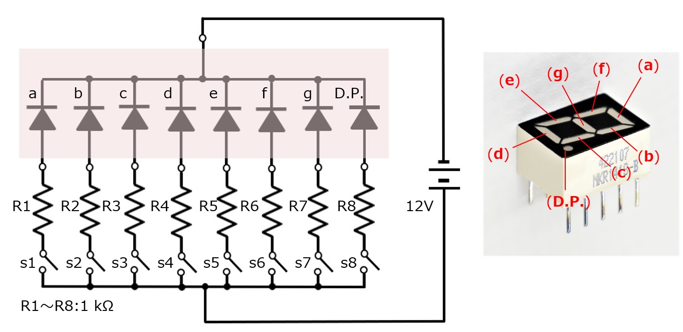
Figure 4. Lighting each segment
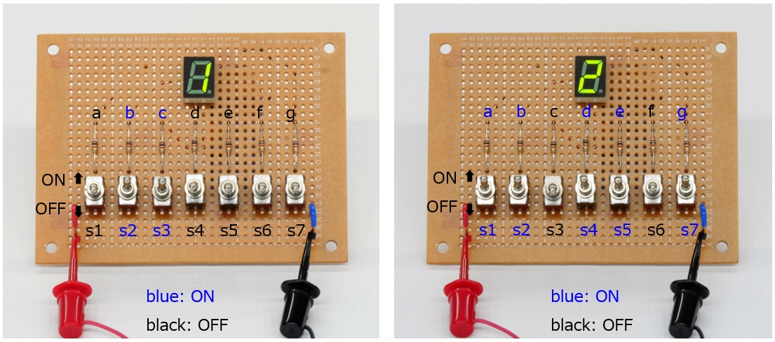
Figure 5. Circuit shown on Figure 4 on PCB
Now turn ON s2 and s3. Segments (b) and (c) light up. This is the number "1." Similarly, if you turn ON the five switches s1, s2, s4, s5, and s7, the number becomes "2." In this way, by lighting one segment with each switch, you can light the numbers 0 to 9 by the combination of lighting each LED segment.
5. Lighting a cathode common LED
To turn the 7 switches ON or OFF to light each segment of the LED, for example, 7 individual outputs are required. BCD (Binary-Coded Decimal) will be introduced here.
The numbers 0 to 9 can be made by adding the four numbers 1, 2, 4, and 8. For example, “5” is the addition of 1 + 4, “7” is the addition of 1 + 2 + 4, and so on. The numbers made with 1, 2, 4, and 8 are called BCD codes. BCD stands for Binary-Coded Decimal. You can use BCD to represent 0 to 9 with four outputs.
There is an IC named TC4511BP. It is a logic IC chip and it commonly functions as a BCD decoder/driver. There are four input leads for BCD codes “1,” “2,” “4,”and “8”, and there are seven outputs for LED segments corresponding of “a” to “g.” TC4511BP outputs the signal which lights the LED corresponding to each number of 7 segment LED, according to the 4 bit input.
The truth table is shown in Figure 6. below. The truth table showing the lighting status of each 7 segment LED for all BCD inputs 0 to 9 is attached at the end of this document for reference.
For reference, if you want to turn on the LED corresponding to “1”, apply an H level to BCD input pin 1 and set the other pins “2,” “4,” and “8” to L level, that is, the ground level. The mechanism is such that b and c light up as the number “1.”
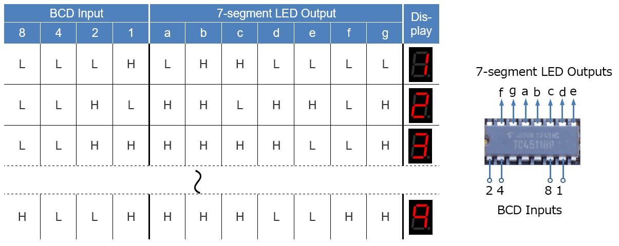
Figure 6. BCD vs 7-segment LED Truth table
6. Lighting the 7-segment LED with the BCD Decoder/Driver IC chip
Figure 7. is the schematic diagram to display a desired number set to the same number on the thumb wheel switch.
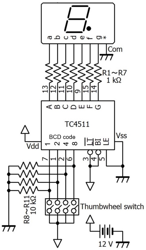
Figure 7. Schematic diagram to display a desired number set to the same number on the thumb wheel switch.
A little special component in the circuit might be a thumbwheel switch that outputs a BCD code. This is a kind of rotary switch in which the voltage of the BCD code corresponding to the display of the thumbwheel switch appears when a voltage is applied to the common terminal on the thumbwheel switch. Figure 8. shows the parts assembled on a universal board. Select the desired number with the thumbwheel switch and the 7-segment LED will display the selected number.
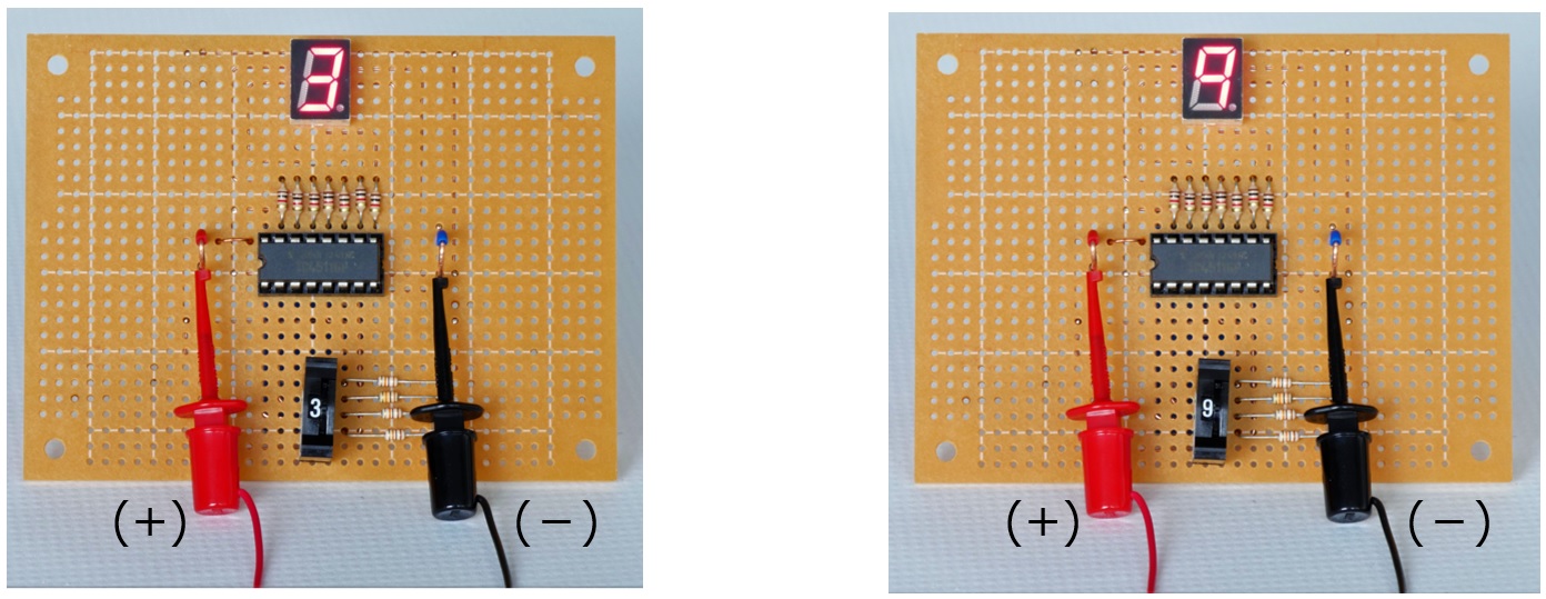
Figure 8. Parts on PCB for the circuit shown in Figure 7
7. Postscript
Most of the displays of the equipment around us are liquid crystal. Since these are driven by a microcomputer, the lighting method is very different from the ones explained this time, but the principle of lighting the 7-segment LED is basically the same as the explanation given.
Now, as the infection with the coronavirus continues to spread, many countries have declared the state of emergency. Even in the contests sponsored by JARL in Japan, neither entry for multi-operators category nor field operations are allowed. We should follow the rules and prevent the spread of the coronavirus as quickly as possible, and we hope that we can make amateur radio field operation possible soon.
FBDX
Technical Trivia by Dr. FB backnumber
- Generating “Sawtooth Waves” using a D/A conversion circuit and a counter IC
- Examining a D/A converter using a Resistor Ladder
- Electronic firefly and its circuit description
- Controlling the rotation speed of a DC motor
- Description of up-down counter using 74HC192 and 74HC4511 ICs
- Considerations when making a dual voltage power supply for operational amplifiers
- Observing filter characteristics with a white noise generator
- Is noise actually reduced in twisted pair cables?
- Experiments on divider circuits using a 74HC74
- Consideration of using a photocoupler as a voltage-variable resistor
- Distorted waveform spectrum as observed on a tinySA
- Trial making of a QFH antenna
- About the inductance of coils
- Operation of analog switches
- Small digital voltmeter, 2-wire type / 3-wire type. What is the difference?
- Constant current circuit using an Op-Amp
- Coaxial cable loss to UHF and SHF
- 2.4 GHz Wireless LAN Antenna
- Let’s use MOSFETS
- 25th Comparator
- The principle of PLL
- Examination of the MLA performance
- About the Fresnel zone of the SHF band
- Level difference under open and load ends of an SSG
- Is “Made in Japan” alive? (UHF adapter again)
- Possibility experiment of passive repeater with the Back-to-Back antenna
- Why you should make SWR measurements just below the antenna!
- How reliable is the L-type BNC?
- Is the Bird 43 accurate enough?
- Does a wire dipole antenna need a balun?
- Why we don’t use a silicon diode in a crystal radio?
- How to light the 7-segment LED
- Measurement of Antenna Performance on Handheld Transceivers (Part 3)
- Measurement of Antenna SWR on Handheld transceivers (Part 2)
- Measurement of Antenna SWR on Handheld transceivers(Part 1)
- An SWR meter
- V/UHF 3-Band Antenna Dismantling Note