


Technical Trivia by Dr. FB
Possibility experiment of passive repeater with the Back-to-Back antenna

Dr. FB
Passive repeater with a hypothetical Back-to-Back antenna
The main propagation modes of the VHF and UHF bands are direct wave line-of-sight, reflected wave, and diffracted wave. For keeping stable communications, there should be no obstacles that interfere with communications between the two communication points. In VHF and UHF band mobile communications, it is difficult to constantly secure these conditions. Therefore, a repeater is installed on a high location, and communication is made through the repeater to secure line-of-sight communication. The role played by repeaters is great, but given the installation and maintenance costs, it always remains a difficult problem for ham radio.
We hypothesized that it might be possible to use two directional antennas instead of a repeater to construct a Back-to-Back (B2B) antenna and operate it as a passive repeater, so we and conducted a field experiment. To determine whether the configuration shown in Figure 1 can be put to practical use as a passive repeater, we would normally first analyze it on paper, by making detailed calculations. However, instead we conducted a field experiment to inspire the amateur spirit.
Unfortunately, the system did not work at all as a passive repeater under the following conditions. The reason why it did not work needs to be analyzed in detail later, but I feel that the signal strength of the signals transmitted from the mobile stations were weak. I would like to try again if we have the opportunity. For now, I will report on the field experiment we made.

Figure 1. Concept diagram of a passive repeater system using a B2B antenna
Hypothesis consideration
Consider when signals are received with a whip antenna and a Yagi antenna, as shown in Figure 2. Signals are transmitted from point A. At the receiving point, the signals are received with a whip antenna and a Yagi antenna, and the signal strength at each antenna is measured with an S-meter. Of course, the S-meter swings more when it is received with the Yagi antenna. This is something that many ham radio operators have experienced without needing to explain it in theory.
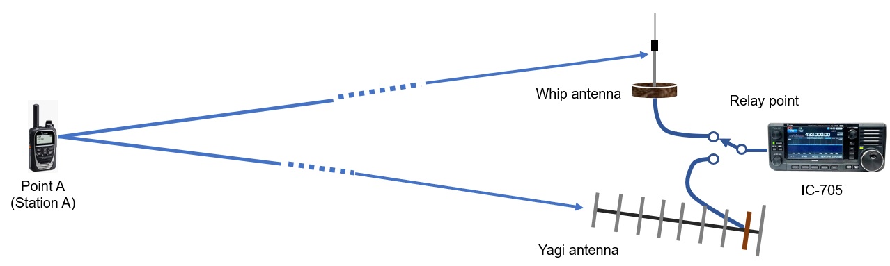
Figure 2. Comparison of a whip antenna and a Yagi antenna
Next, consider retransmitting the received ultra-weak signals from the antenna with the strongest possible radio waves without using an amplifier. We know that it is possible to radiate stronger signals in a specific direction using a Yagi antenna instead of a whip antenna, as shown in Figure 3. This is the same as the communication called QRP on amateur radio. The ultra-weak signals are the signals received by the whip antenna or the Yagi antenna, not the signals generated by a signal generator.
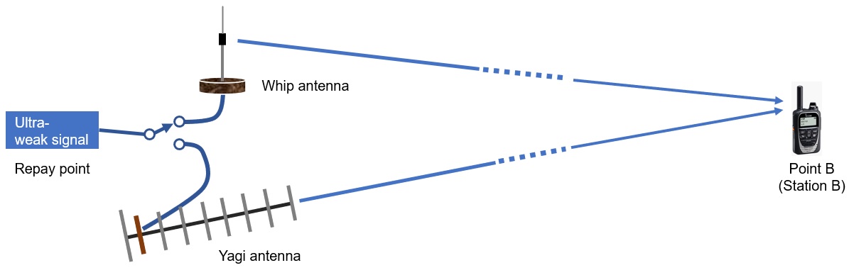
Figure 3. Transmits ultra-weak radio waves far away
B2B antenna production
To make the B2B antenna, I chose the A430S10R2 10-element Yagi antenna from the Japanese antenna manufacturer, Diamond Antenna Corporation, because it is lightweight enough to carry it to the top of the mountain and has appropriate gain. I bought two antennas and assembled them so that their backs were close together, as shown in the photo below. When assembling, I also mounted them at a slight downward elevation angle so that they could be pointed toward the station points.
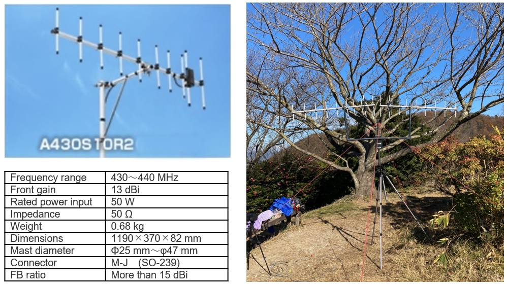
Figure 4. B2B antenna
Field preliminary experiment
We suddenly made a field experiment without any prior on-paper calculations. The geographical relationship between the mobile locations and the relay station is shown in Figure 6. The experiment started at 1000JST on December 2, 2020. The frequency was 438.03MHz DV simplex, with station A on the Osaka prefecture side of the relay point and station B on the Nara prefecture side. Both mobile stations stood by each point with an ID-31 and an IC-705. First, from the relay point, I confirmed that station A and station B could not communicate directly.
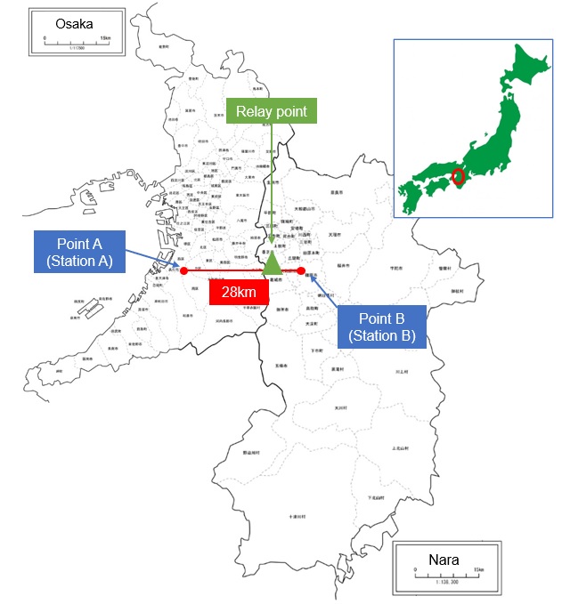
Figure 5. Locations of points A, the relay point, and point B
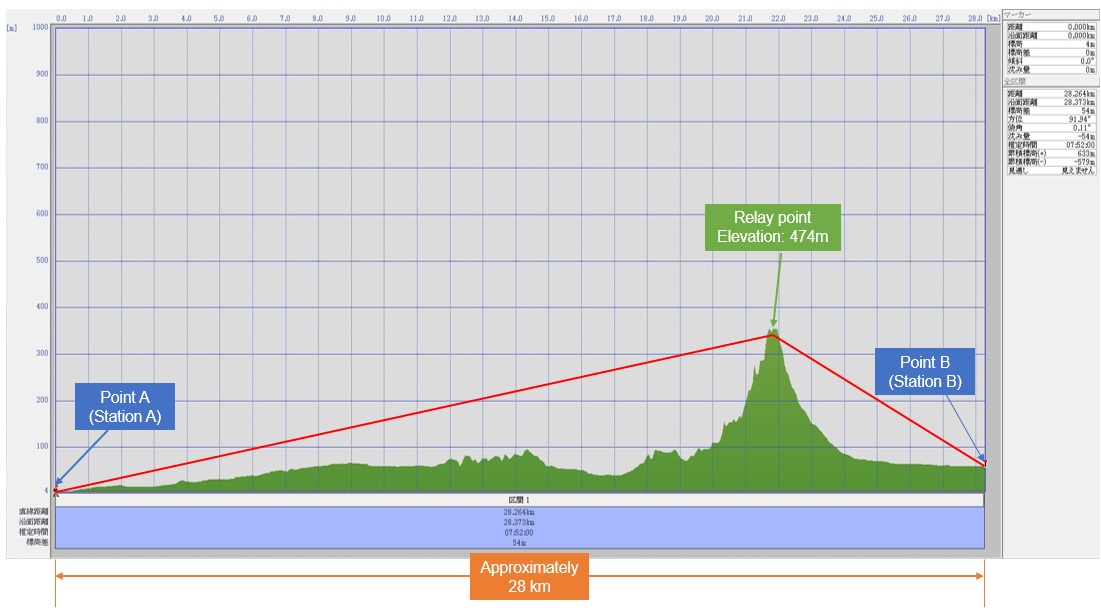
Figure 6. Cross-sectional view between the three points
At first, I removed the coaxial cable that connects the B2B antenna and started the experiment without operating the B2B antenna. In the experiment, we decided to confirm the effect of the 13 dBi performance of the Yagi antenna, and how much signal strength can be communicated with points A and with point B. We used an NR770R antenna from Diamond Antenna. This is a mobile whip antenna that covers both the VHF and UHF bands, but in this experiment, only the UHF band was used. According to the manufacturer's specifications, the UHF band is constructed as a 5/8λ, a two-stage non-radial type antenna, with a gain of 5.5 dBi.
The preliminary experiment began by checking each station’s signal strength with an S-meter, as shown in Figure 7 and Figure 8. While checking, there was no so-called R2D2 sound when the digital signal strength was low, and communication was clear.
When I transmit at 5 watts from the relay point with the ID-31on a whip antenna, the S-meter indications at the point A and point B did not reach full scale, but they indicate full scale with the Yagi antenna. We can see that the effect of the Yagi antenna is great. It was hypothesized that if 5 watts was transmitted from the relay point, some kind of signal could be received at points A and B even if points A and B cannot receive it clearly.
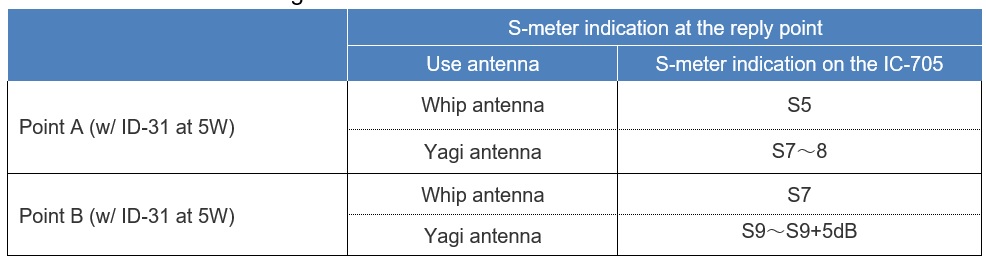
Figure 7. The S-meter indication of each station’s transmitted signal at the relay point

Figure. 8. The S-meter indication of the relay point’s transmitted signal at each station point
Field experiment and results
The relay cable for the B2B antenna shown in Figure 5 was connected, and the horizontal angle was set to 90 ° on the east side and 270 ° on the west side using a compass. Also, the beam pattern of the B2B antenna used is not as sharp as a parabolic antenna, but it is still set to the negative elevation angle calculated in advance from the distance and altitude. The calculation is shown in Figure 9.
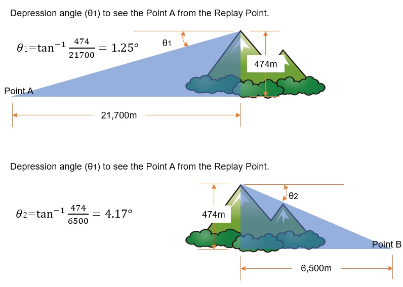
Figure 9. Calculation of the depression angle
We called each other several times from station A to station B, and vice versa, but there was no response from the other station to any of the calls, and it was found that the radio waves did not reach the stations at all. This means that our B2B antenna was not successful as a passive repeater. This may not a problem with the antenna, but a problem with the gain and transmission power of the antennas used at points A and B. If there was a spectrum analyzer at the relay point, I could measure the signal strength, but this time I could not prepare it, unfortunately.
Next, I tried using the SSB mode, which has a much better S/N ratio than DV and FM. Both A and B stations changed their equipment to the IC-705 and the whip antenna. I watched to see if I could see white lines on the waterfall screen indicating a signal, but I could not see anything. In other words, it was not possible to relay even an SSB signal.
Although the IC-705 is a portable all band and all mode radio, it has the same waterfall function as a large, fixed radio, so it can also be used as a simple measuring instrument like I did this time. This is a very convenient function because you can visually observe if a signal is received on the waterfall screen.
Stations A and B made calls to each other to check various communication possibilities in the SSB, DV and FM modes, but in all cases, the B2B antenna did not function as a passive repeater.
Considerations
A fairly strong signal is required to detect the received signal and demodulate it into audio in the DV or FM mode. This time, it suddenly became a field experiment without prior on-paper calculations, and it was not possible to relay with the B2B antenna, so the experiment ended in failure.
It may be possible to make a communication in SSB or CW, even only with signal strength of one digit on the S-meter. However, I guess that the antenna input needs a signal strength of minus several dBµ.
In other words, in order to transmit from the relay point and to induce a voltage of minus several dBµ at the receive station’s antenna 20 km away, how many watts should be transmitted, or what gain should the antenna have? To know these answers, it seems that we can calculate them on paper. Alternatively, if you use FT8 or JT65 modes, you may be able to communicate without putting out too much power or using an antenna with a lot of gain. This is a very interesting theory. Next time, I would like to conduct another experiment after doing more preparation in advance.
FBDX
<Reference>
Antenna specifications: Quoted from the website of Diamond Antenna Corporation
Map: (triangular blank map processed based oOsaka and Nara prefectures) (processed by quoting the data created in the introduction to Kashmir 3D by Jitsugyo No Nihonsha)
Map: “Illust Box” Free map
Technical Trivia by Dr. FB backnumber
- Generating “Sawtooth Waves” using a D/A conversion circuit and a counter IC
- Examining a D/A converter using a Resistor Ladder
- Electronic firefly and its circuit description
- Controlling the rotation speed of a DC motor
- Description of up-down counter using 74HC192 and 74HC4511 ICs
- Considerations when making a dual voltage power supply for operational amplifiers
- Observing filter characteristics with a white noise generator
- Is noise actually reduced in twisted pair cables?
- Experiments on divider circuits using a 74HC74
- Consideration of using a photocoupler as a voltage-variable resistor
- Distorted waveform spectrum as observed on a tinySA
- Trial making of a QFH antenna
- About the inductance of coils
- Operation of analog switches
- Small digital voltmeter, 2-wire type / 3-wire type. What is the difference?
- Constant current circuit using an Op-Amp
- Coaxial cable loss to UHF and SHF
- 2.4 GHz Wireless LAN Antenna
- Let’s use MOSFETS
- 25th Comparator
- The principle of PLL
- Examination of the MLA performance
- About the Fresnel zone of the SHF band
- Level difference under open and load ends of an SSG
- Is “Made in Japan” alive? (UHF adapter again)
- Possibility experiment of passive repeater with the Back-to-Back antenna
- Why you should make SWR measurements just below the antenna!
- How reliable is the L-type BNC?
- Is the Bird 43 accurate enough?
- Does a wire dipole antenna need a balun?
- Why we don’t use a silicon diode in a crystal radio?
- How to light the 7-segment LED
- Measurement of Antenna Performance on Handheld Transceivers (Part 3)
- Measurement of Antenna SWR on Handheld transceivers (Part 2)
- Measurement of Antenna SWR on Handheld transceivers(Part 1)
- An SWR meter
- V/UHF 3-Band Antenna Dismantling Note