


Technical Trivia by Dr. FB
Controlling the rotation speed of a DC motor
Experiment with N-channel MOSFET devices

Dr. FB
When a battery is connected to a DC motor, the motor rotates. Changing the voltage applied to the motor will change the rotation speed. Any power supply with a variable voltage can be used, but if the voltage is constant, such as a dry cell battery, some control circuit is needed to change the speed. Each of the circuits I experimented with in this project will be helpful when building models using DC motors.
Variety of DC motor speed control circuits
I have experimented with and discussed the four types of circuits described below.
(1) Variable voltage applied to a DC motor using a variable resistor
(2) Interrupting the voltage applied to a DC motor using a logic ICs
(3) Variable duty cycle of the voltage applied to a DC motor using a timer IC (NE555)
(4) Control the current flowing to the DC motor with a MOSFET device
The DC motor used in the experiment was rated for a voltage range of 2.5 to 3.5 V, according to the specifications. The current at no load was about 0.12 A (=120 mA) when 3 V was applied. When the 12 cm diameter disk made of cardboard shown in the Short Break article was attached to the shaft and rotated, the motor was loaded, and the current increased quickly to about 1.5 A. The torque of the DC motor changed according to the change in load. The torque of the DC motor changes according to the change in load, and the current flowing through the motor also changes.
Method using a variable resistor
Figure 1 shows a simple circuit with a variable resistor connected between the power supply and the motor. This is the simplest and most reliable method, but it does not mean that any variable resistor can be used. This is the bottleneck.
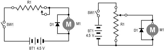
Figure 1. Connecting a variable resistor into the circuit
When a motor rotates, current flows, which is 0.12 A with no load, as mentioned above. The AF volume used in communication equipment, audio equipment, and so on, is made of carbon coated on a disc and used as a resistive element (carbon track). A contact point called the sliding contact moves over the carbon track, changing the resistance value (Figure 2).
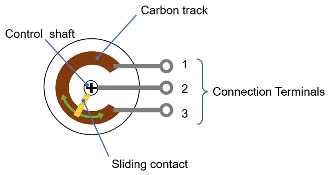
Figure 2. Structure of variable resistor
In this case, if the circuit is as shown in Figure 1, at least 0.12 A flows through the carbon track when the motor rotates, and the carbon used as the carbon track will burn out because a current greater than the specification flows through it. Therefore, the use of wire-wound variable resistors, which can carry more current is considered. However, this wire-wound variable resistor is very expensive and is a bottleneck.
Intermittent voltage applied to a DC motor using a logic
This method uses a switch to turn the voltage applied to the motor ON and OFF. It is difficult to manually turn ON and OFF quickly using a physical switch. Here, the voltage applied to the motor is intermittent with a transistor. The voltage applied to the motor is generated by an oscillator in inverters in a logic IC, and the transistor is turned ON and OFF at its output.
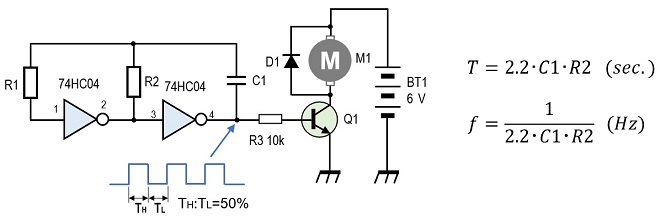
Figure 3. Intermittent voltage applied to the motor using an inverter IC
By using the above formula and changing the values of capacitance and resistance in the circuit, the output frequency of the oscillator (f) or the cycle (T) to turn the motor ON and OFF can be changed. When the output of the oscillator is high (H), Q1 turns ON and the motor rotates, and when it is low (L), Q1 turns OFF and the motor rotates by inertia, but the speed gradually decreases. This is a repetition. Since the transistor is used in the saturation region, voltage is applied or not applied to the motor depending on whether the signal applied to the base is H or L.
For your reference, if the values of each component in the circuit shown in Figure 3 are set as follows, the transistor ON/OFF cycle (T) is approximately 0.1 second.
R1=470 kΩ (the value of R1 should be approximately 10 times that of R2)
R2=47 kΩ
C1=1 µF
The principle is that if R2 is used as a variable resistor, the ON/OFF cycle of the motor can be varied, and the rotation speed of the motor can be varied.
As a result of the experiment, the motor did not rotate smoothly because the time between TH and TL is longer when the oscillation frequency is low, and the interval between ON/OFF of the motor is also longer. Smooth rotation can be expected if, for example, a flywheel is inserted to the motor shaft.
Also, as the frequency is increased, the transistor electrically turns ON and OFF repeatedly, but the motor does not respond and the rotation speed is uncontrollable. The idea was good, but the result was not good enough.
Using a timer IC to vary the duty ratio of the voltage applied to the motor
I tried the circuit shown in Figure 4 using the timer IC chip such as an NE555 to vary the duty ratio of the output signals TH and TL of the circuit shown in Figure 4 significantly. The circuit is called an unstable multivibrator. I guessed that the motor would rotate smoothly by making TH longer and TL shorter in the ON/OFF duty ratio of the motor.
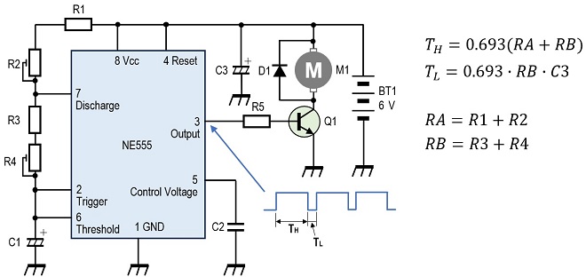
Figure 4. Using an NE555 to vary the duty ratio of the voltage applied to the motor
The rotation of the motor was not smooth, as in the circuit in Figure 3, because the TH had to be shortened in order to make the motor rotate at a low speed. As with the circuit in Figure 3, the intermittent rotation of the motor could be absorbed by attaching a flywheel to the shaft, although I have not conducted any experiments.
Controlling the current in a DC motor with a MOSFET
To attach a relatively light load to the shaft of the motor and make it rotate smoothly, it seems essential to continuously change the voltage or current applied to the motor without interruption. The circuit shown in Figure 2 above, in which a variable resistor is installed, is just such a circuit, and the circuit shown in Figure 5 attempts to realize this in an electronic circuit. I tried a circuit using an N-channel (N-ch) MOSFET, focusing on smooth and continuous control of rotation without using a flywheel or gears.
The LM358 (IC1) is a general-purpose operational amplifier that operates on a single power supply. D1 is a 2.6 V Zener diode. The voltage on pin 3 of the IC1 is divided by R2 and R3, and the IC1 compares the voltage on pin 3 with the voltage on pin 2 and outputs a positive voltage from pin 1 if the voltage on pin 3 is higher. The output voltage turns ON 2SK2232(Q1) and the motor rotates.
Since Q1 is an N-ch MOSFET, when a positive voltage is applied to the gate, the drain-source resistance (RDS) of the MOSFET decreases, resulting in the so-called ON state. Originally, this circuit is used to maintain a constant current flowing to the motor to keep the rotation speed constant, but here, the rotation speed of the motor is controlled by changing the RDS by varying the reference voltage.
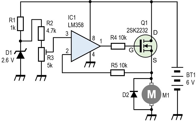
Figure 5. Current flowing in a DC motor is controlled by a MOSFET.
The two types of MOSFETs used in the experiment are shown in Figure 6. The 2SK2232 results were outstanding in the results. The STP75NF75 was not suitable for this experimental circuit because it did not provide enough motor rotation. The important specification for MOSFET performance is the RDS of the MOSFET when it is in the ON stage. When a positive voltage is applied to the gate, the RDS of the MOSFET is low. The lower the RDS, the better the current flow. According to the specification sheet, the RDS of the 2SK2232 is 36 mΩ, while that of the STP75NF75 is 11 mΩ, about 1/3 lower than the former. I was attracted by this low RDS, but the motor speed did not increase even when the MOSFET was turned ON.
I verified the circuit but could not find the cause, and my verification concludes that the STP75NF75 used happened to be out of specifications. Since I had no spare component in hand, I could not replace it and experiment again. At any rate, when I replaced the MOSFET with a 2SK2232, the rotation became extremely high.
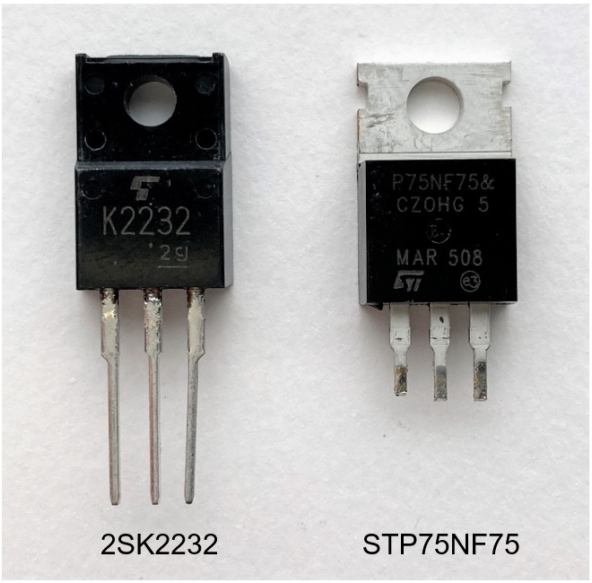
Figure 6. N-ch MOSFET used in motor speed control experiment
The voltage at both terminals of the motor was 3.5 V and the drain current was 0.15 A with no load. When the motor was rotated with a disc attached and a load applied, the drain current increased to approximately 1.6 A. When the motor is rotated at high speed for a long time, the MOSFET emits heat, so it is necessary to install a heat sink.
Also, it is possible that the component values shown in Figure 5 do not apply to the type of motor used, so a certain amount of cut-and-try is necessary. Figure 7 shows an experimental board that uses a MOSFET to control a DC motor.
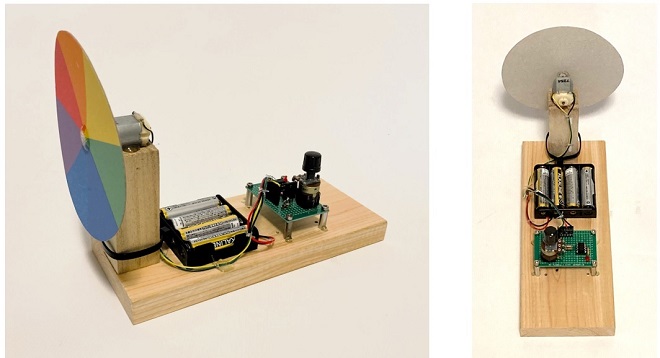
Figure 7. Experimental board with N-ch MOSFET
FBDX
<References>
The control circuit using a MOSFET can be found in the articles shown below.
Technical Trivia by Dr. FB from the monthly FB news
Let's use MOSFETS
Understanding the switching function of MOSFET transistors
https://fbnews.jp/202108/w_trivia/
Short Break from the monthly FB news
Building a 20 Amp electronic DC load device using an N-channel MOSFET for the load
https://www.fbnews.jp/202110/w_shortbreak/
Short Break from the monthly FB news
Electronics project for the 10 MHz reference signal generator
Part 1: https://www.fbnews.jp/202203/w_shortbreak/
Part 2: https://www.fbnews.jp/202204/w_shortbreak/
Technical Trivia by Dr. FB backnumber
- Generating “Sawtooth Waves” using a D/A conversion circuit and a counter IC
- Examining a D/A converter using a Resistor Ladder
- Electronic firefly and its circuit description
- Controlling the rotation speed of a DC motor
- Description of up-down counter using 74HC192 and 74HC4511 ICs
- Considerations when making a dual voltage power supply for operational amplifiers
- Observing filter characteristics with a white noise generator
- Is noise actually reduced in twisted pair cables?
- Experiments on divider circuits using a 74HC74
- Consideration of using a photocoupler as a voltage-variable resistor
- Distorted waveform spectrum as observed on a tinySA
- Trial making of a QFH antenna
- About the inductance of coils
- Operation of analog switches
- Small digital voltmeter, 2-wire type / 3-wire type. What is the difference?
- Constant current circuit using an Op-Amp
- Coaxial cable loss to UHF and SHF
- 2.4 GHz Wireless LAN Antenna
- Let’s use MOSFETS
- 25th Comparator
- The principle of PLL
- Examination of the MLA performance
- About the Fresnel zone of the SHF band
- Level difference under open and load ends of an SSG
- Is “Made in Japan” alive? (UHF adapter again)
- Possibility experiment of passive repeater with the Back-to-Back antenna
- Why you should make SWR measurements just below the antenna!
- How reliable is the L-type BNC?
- Is the Bird 43 accurate enough?
- Does a wire dipole antenna need a balun?
- Why we don’t use a silicon diode in a crystal radio?
- How to light the 7-segment LED
- Measurement of Antenna Performance on Handheld Transceivers (Part 3)
- Measurement of Antenna SWR on Handheld transceivers (Part 2)
- Measurement of Antenna SWR on Handheld transceivers(Part 1)
- An SWR meter
- V/UHF 3-Band Antenna Dismantling Note