


Technical Trivia by Dr. FB
Level difference under open and load ends of an SSG

Dr. FB
When I was young, there was a time when the receiving system used dBµ to describe the signal level and the transmitting system used dBm. However, when foreign-made SSGs (Standard Signal Generators) came into Japan, use of the dBm notation increased. I remember that I suddenly started using dBm one day. (SSG hereafter abbreviated SG)
In this article, I will talk about the relationship between µV, mW, dBµ, and dBm. Also, when I, Dr. FB started amateur radio, I wondered why if I connect a load to the DC power supply terminal the terminal voltage does not drop, but why the terminal output level goes down when a load is connected to the SG output terminal? I will talk about this wonder in this article.
Relationship between dBµ and dBm
In tele-communication systems, the following two notations are often used as units to express the signal level.
1. dBµ uses 1 µV as the 0 dB reference
2. dBm uses 1 mW as the 0 dB reference
Now let's examine the relationship between dBµ and dBm. First, I will explain dBm. Let’s connect a 50 Ω load to the output terminal of the SG, as shown in Figure 1. The SG signal level is defined as 0 dBm when 1 mW of power is consumed on the 50 Ω load. In other words, 0 dBm means 1 mW. Furthermore, 10 mW is 10 dBm, and 100 mW (= 0.1 W) is 20 dBm.
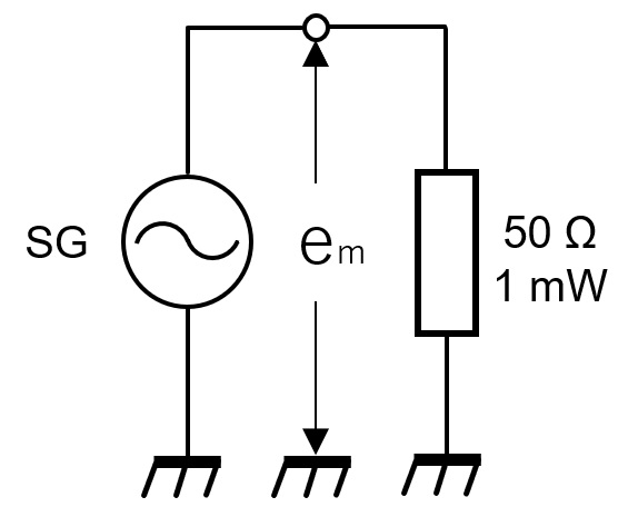
Figure 1. Definition of 1 dBm
Next, in order to consider the relationship with dBµ, let's calculate the voltage, em, generated across the 50 Ω load that is the SG output level. It can be calculated as an extension of Ohm's law. Since 1 mW is consumed in a load of 50 Ω, the power, P, can be derived from equation (1) from the voltage and the value of the load. Equation (2) is the equation obtained by finding em from equation (1).

Here, P = 1 mW = 1 × 10⁻³, R = 50, so when em is calculated, em = 0.224 V as shown in equation (2).

I mentioned earlier that the unit of dBµ defines 1 µV as 0 dB. The voltage level for 0.224 V, that is, 1 mW, which was calculated by the above equation (2), was calculated by the following equation (3), which was 107 dB. Since 1 µV is defined as 0 dB, 107 dB is also 107 dBµ, and the reference level, the letter “µ” is added after dB to express what the reference is in an easy-to-understand manner.

Conversely, if 1 µV is expressed in dBm, it will be −107 dBm as shown in equation (4). This also takes the letter “m” of 1mW and adds “m” after dB to make it dBm so that you can see that 1mW is the standard. Logarithm calculations cannot be done without a scientific calculator at this point.

About the open end and the load end
A brief diagram is shown in Figure 1 above to investigate the relationship between dBµ and dBm. However, when considering the open end voltage and load end voltage of the SG output, the equivalent circuit on the SG side is inaccurate in Figure 1. And, as I mentioned at the beginning of this article, the problem is that the level drops when the load is connected. It cannot be used as a solution. When looking at inside the SG from the output side of the SG, the output impedance of the SG we usually use is 50 Ω. Therefore, it can be said that a general equivalent circuit is drawn as shown in Figure 2.
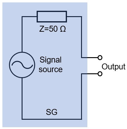
Figure 2. Equivalent circuit of a general signal generator
A load with an impedance of 50 Ω is connected to the SG equivalent circuit depicted in Figure 2, but the 50 Ω is not actually connected as an independent component in an SG, and is an internal impedance. For simplicity, let's assume that the voltage level of the signal source is 2 V and no load is connected with the SG output terminals. Consider how many volts will be at the output terminals. The answer is 2 V, the same level as the signal source. It is difficult to understand.
Although the impedance of 50 Ω is connected inside of the SG as an equivalent circuit, no current flows in the circuit because nothing is connected to the output terminals. At the output of the SG, the voltage appears even when no load is connected to the output terminal. Now, let's connect a 50 Ω load to this output end. The load will be referred to as ZL. The circuit at that time is as shown in Figure 3(a), and if it is rewritten in an easy-to-understand manner, it will be as shown in Figure 3(b). Figures 3(a) and (b) have different shapes, but the same circuit.
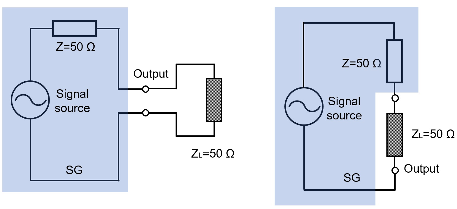
Figure 3. Equivalent circuit when a 50 Ω load is connected
The voltage level of the SG signal source was assumed to be 2 V. As you can see in Figure 4, that 2 V is applied to both ends of the Z and ZL connection. In other words, the voltage across Z is 1 V, and the voltage across ZL is also 1 V. Expressing half of the voltage level in decibels is -6 dB. The calculation shows it in equation (5) below.

Verification that the voltage level is halved when a 50Ω load is connected
Generate a 10 MHz unmodulated sine wave in SG. Observe the waveforms with and without a 50 Ω dummy load connected to the SG output with an oscilloscope.
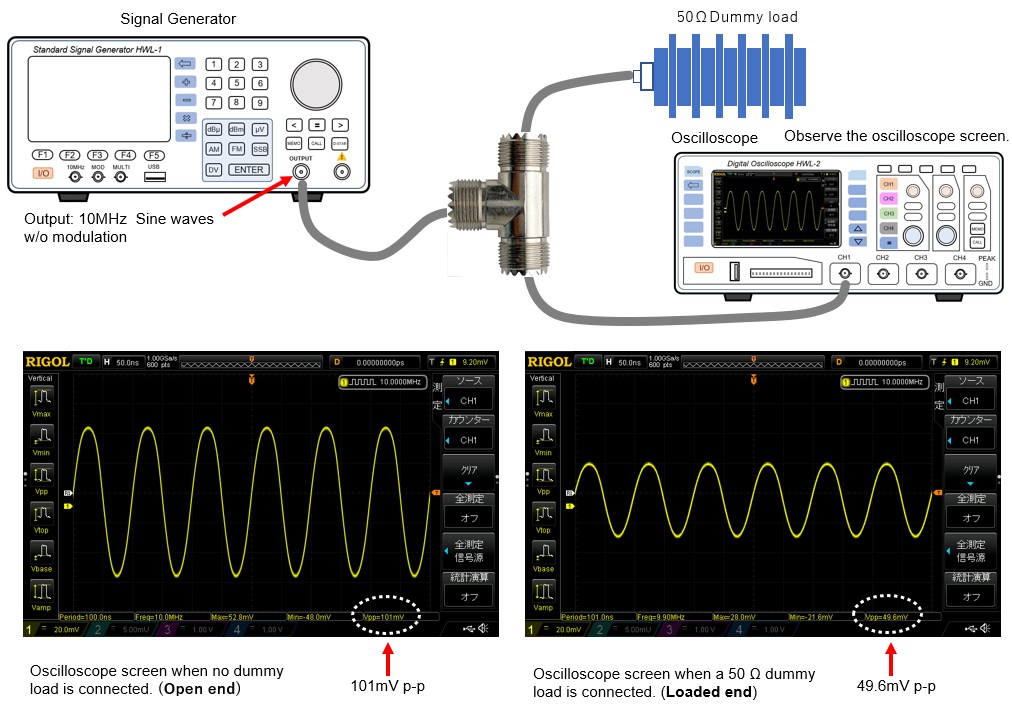
Figure 4. Observe signal level on the oscilloscope screen
In Figure 5, the peak-peak (p-p) of the waveform when the dummy load is not connected (no load / open end) was about 101 mV. With a 50 Ω dummy load connected, the output level at its load end was 49.6 mV. As calculated, you can see that the SG output has been halved.
FBDX
Technical Trivia by Dr. FB backnumber
- Generating “Sawtooth Waves” using a D/A conversion circuit and a counter IC
- Examining a D/A converter using a Resistor Ladder
- Electronic firefly and its circuit description
- Controlling the rotation speed of a DC motor
- Description of up-down counter using 74HC192 and 74HC4511 ICs
- Considerations when making a dual voltage power supply for operational amplifiers
- Observing filter characteristics with a white noise generator
- Is noise actually reduced in twisted pair cables?
- Experiments on divider circuits using a 74HC74
- Consideration of using a photocoupler as a voltage-variable resistor
- Distorted waveform spectrum as observed on a tinySA
- Trial making of a QFH antenna
- About the inductance of coils
- Operation of analog switches
- Small digital voltmeter, 2-wire type / 3-wire type. What is the difference?
- Constant current circuit using an Op-Amp
- Coaxial cable loss to UHF and SHF
- 2.4 GHz Wireless LAN Antenna
- Let’s use MOSFETS
- 25th Comparator
- The principle of PLL
- Examination of the MLA performance
- About the Fresnel zone of the SHF band
- Level difference under open and load ends of an SSG
- Is “Made in Japan” alive? (UHF adapter again)
- Possibility experiment of passive repeater with the Back-to-Back antenna
- Why you should make SWR measurements just below the antenna!
- How reliable is the L-type BNC?
- Is the Bird 43 accurate enough?
- Does a wire dipole antenna need a balun?
- Why we don’t use a silicon diode in a crystal radio?
- How to light the 7-segment LED
- Measurement of Antenna Performance on Handheld Transceivers (Part 3)
- Measurement of Antenna SWR on Handheld transceivers (Part 2)
- Measurement of Antenna SWR on Handheld transceivers(Part 1)
- An SWR meter
- V/UHF 3-Band Antenna Dismantling Note