


Technical Trivia by Dr. FB
Description of up-down counter using 74HC192 and 74HC4511 ICs
Dr. FB
This is an addition to the "Radio Geek" article “Making an Up/Down counter (1)” in last month’s issue of this web magazine. This article provides supplementary explanations about the ICs and 7-segment LED used in the up-down counter.
Relationship between BCD and decimal
Figure 1 shows a block diagram of a single-digit up-counter using the 74 series ICs. IC1 (74HC192) is an IC that is presetable synchronous 4-bit up-down counter and represents the number of clock signals in BCD. IC2 (74HC4511) is an IC that directly drives a 7-segment LED from the BCD (Binary Coded Decimal) signal.

Figure 1. Block diagram of the up counter using an IC 74HC192
As an example, suppose that three clock signals are input to the clock input of IC1. Three signals, "LLHH" representing “3” in BCD appear at the output pins Q0~Q3 of IC1 where L is 0 V (GND level) and H is 5 V, almost the same as the supply voltage. This is expressed in BCD or binary numbers as "0011."
Q0: L (0)
Q1: L (0)
Q2: H (1)
Q3: H (1)
The IC2 (74HC4511) is a 7-segment decoder that converts A to D BCD inputs into a 7-segment display. When all 4 bits are "L," the BCD notation is "0000," and the 7-segment LEDs light up with the number "0." When all 4 bits are "H," the BCD notation is "1111," which means "15."
Since it is 4 bits, it can represent numbers to the fourth power of 2, from 0 to 15. As it is a one-digit counter, it cannot express more than 10 in decimal, but it can be expressed in hexadecimal, as shown in the table below.
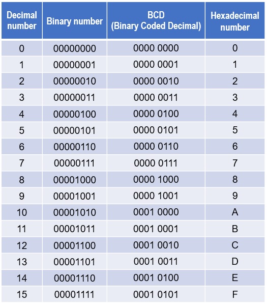
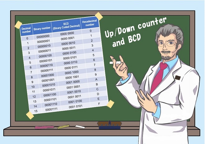
Figure 2. Representation of binary, BCD, and hexadecimal numbers relative to decimal numbers
IC2 receives the number of clock signals in BCD format, and outputs them with signals for the 7-segment LEDs a~g. The corresponding table is shown in Figure 3.
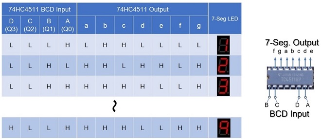
Figure 3. Relationship between BCD input and 7-segment output
Output signals on IC2 as Active-High
When output pins a~g of IC2 are set H, the output is applied to the 7-segment LEDs through a 330 Ω resistor, and each segment of the LEDs lights up. The 330 Ω resistor serves to limit the current flowing to the LEDs. When the output is H, the LEDs light up, and this output is called active "H" (Active High). When working a logic circuit with ICs, you may encounter active-low and active-high pins. This simply means how the pin is activated. This active H affects the type of 7-segment LED connected after this IC. Details are described below.
About BCD(Binary Coded Decimal)
BCD is a way of expressing numbers that have properties between those of binary and decimal numbers. For single-digit numbers in decimal (0~9), binary notation and BCD notation are the same, but for numbers with two or more digits, they differ. BCD is a method of expressing a decimal number by dividing it into individual digits, each of which is represented by a binary number.
Representing 15 in 4 binary bits gives “1111,” and 8 bits gives “00001111.” Similarly, 15 expressed in BCD is divided into 1 in the tens place and 5 in the ones place in binary, so the tens place is 1 and the ones place is 5. Each digit is expressed in 4 bits, as shown below. (See Figure 2) BCD notation for 15 is "0001 0101."
10 place (1):0001
1 place (5): 0101
Active-High and a cathode common LED
IC2 (74HC4511), which drives the 7-segment LED, is an active-H IC. In other words, the output when each pin a~g goes H is used to light the 7-segment LED, so you can see that the 7-segment LED must be a cathode common LED, as shown in Figure 4.
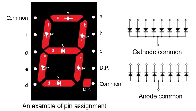
Figure 4. Two types of 7-segment LED as a cathode common LED and anode common LED
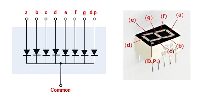
Figure 5. 7-segment LED (cathode common)
For the cathode common LED shown in Figures 4 and 5, the cathodes of all diodes are bundled together and connected to GND (Common), and the anodes of each diode are connected to IC2 a~g separately through current limiting resistors. If the power supply voltage is 5 V, a resistor value of about 330 Ω is appropriate.
FBDX
Technical Trivia by Dr. FB backnumber
- Generating “Sawtooth Waves” using a D/A conversion circuit and a counter IC
- Examining a D/A converter using a Resistor Ladder
- Electronic firefly and its circuit description
- Controlling the rotation speed of a DC motor
- Description of up-down counter using 74HC192 and 74HC4511 ICs
- Considerations when making a dual voltage power supply for operational amplifiers
- Observing filter characteristics with a white noise generator
- Is noise actually reduced in twisted pair cables?
- Experiments on divider circuits using a 74HC74
- Consideration of using a photocoupler as a voltage-variable resistor
- Distorted waveform spectrum as observed on a tinySA
- Trial making of a QFH antenna
- About the inductance of coils
- Operation of analog switches
- Small digital voltmeter, 2-wire type / 3-wire type. What is the difference?
- Constant current circuit using an Op-Amp
- Coaxial cable loss to UHF and SHF
- 2.4 GHz Wireless LAN Antenna
- Let’s use MOSFETS
- 25th Comparator
- The principle of PLL
- Examination of the MLA performance
- About the Fresnel zone of the SHF band
- Level difference under open and load ends of an SSG
- Is “Made in Japan” alive? (UHF adapter again)
- Possibility experiment of passive repeater with the Back-to-Back antenna
- Why you should make SWR measurements just below the antenna!
- How reliable is the L-type BNC?
- Is the Bird 43 accurate enough?
- Does a wire dipole antenna need a balun?
- Why we don’t use a silicon diode in a crystal radio?
- How to light the 7-segment LED
- Measurement of Antenna Performance on Handheld Transceivers (Part 3)
- Measurement of Antenna SWR on Handheld transceivers (Part 2)
- Measurement of Antenna SWR on Handheld transceivers(Part 1)
- An SWR meter
- V/UHF 3-Band Antenna Dismantling Note