


Technical Trivia by Dr. FB
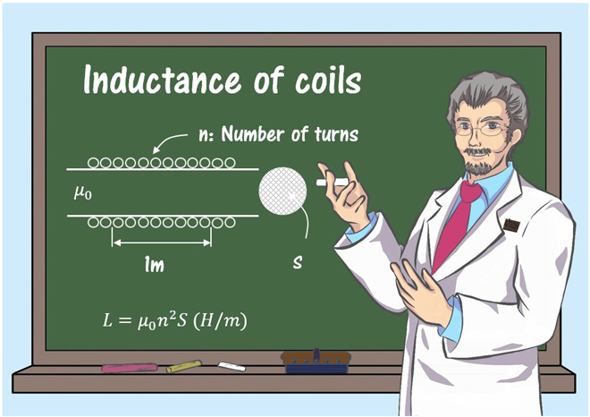
About the inductance of coils
Dr. FB
Resistors, coils (hereafter called inductors), and capacitors are essential components in electronic circuits. Both resistors and capacitors have their values printed on the surface of each component, but many inductors do not have such printing on them, and to working with inductors is troublesome for electronics project fans. I did a simple experiment on the inductors of an LC resonant circuit that is installed in an RF amplifier section when I built a medium wave radio, so I will introduce it.
Four types inductors
The inductors used in the experiment are (a) through (d) in Figure 1. One inductor is used in an LC parallel resonance circuit. It is connected to a variable capacitor in parallel, and functions to select a desired broadcasting station.
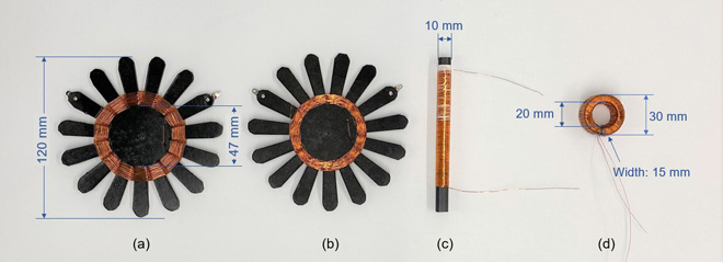
Figure 1. The four types of coils used in the experiment.
The diameter of the enameled wire used for the inductors is Žå0.321 mm, shown in Figure 2, and the length is 8.3 m. The actual measured DC resistance is 2.1 ╬®. The mounts used for the inductors (a) and (b) were made of thick paper glued together. The thickness of the mount paper is about 1 mm. These inductors are often called a spiderweb coil because of its spider web appearance.
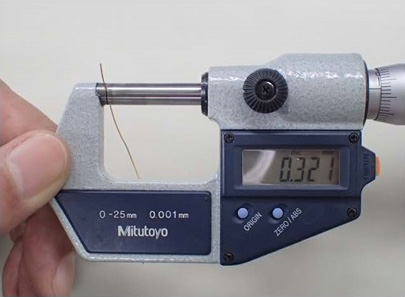
Figure 2. Measurement of the enameled wire diameter (Picture: JH3OTD)
(c) is a ferrite rod with a diameter of 10 mm and a length of 120 mm. I do not know the permeability and other data other than the physical length. Same as the inductor for (d), I do not know the detailed data.
Investigation - Part 1 (Winding the spiderweb inductor)
The inductors shown in Figures 1(a), (b), and (c) are often used in germanium radios when they are connected in an LC parallel resonance circuit. When you buy a germanium radio kit, the instruction manual shows how you wind the inductor. There seem to be two main ways of winding the inductors, (a) and (b). I was wondering how this winding method affects the reception of the germanium radio, so I decided to investigate.
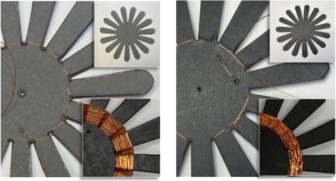
Figure 3. Left: Single-skip winding, Right: Double-skip winding
There are 15 blades on the mount that I made. As I started winding the inductor, I realized that the odd number of blades is the key point. On the left side of the inductor, I wound the enameled wire on each blade alternately such as front to back, back to front, and so on. I call this winding single-skip winding here in this article. On the right side, I wind the wire around two blade skips. I called this winding double-skip winding. The completed inductors are shown in Figure 1(a) and (b).
(1) Measuring inductance
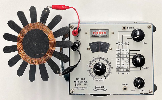
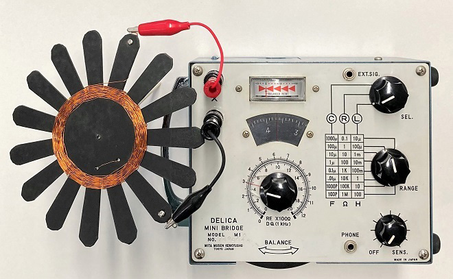
I measured the inductance with an impedance bridge, shown in Figure 3, and found that the inductance was about 350 ┬ĄH regardless of the winding method, either single-skip or double-skip winding.
(a) Single-skip winding
(b) Double-skip winding
(2) Checking the receive sensitivity with each inductor
I connected inductors (a) and (b) I made, one with a single-skip winding and the other with a double-skip winding, to the inductor section of a germanium radio, and checked the receive sensitivity. The results showed that there was no difference between the two inductors.
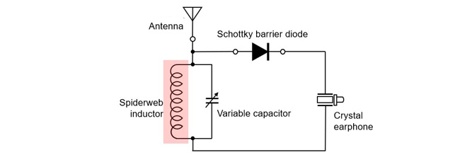
Figure 5. Checking the performance of the spiderweb inductor with a germanium radio
(3) Difference between the two winding methods
The difference in the diameter of the inductor when wound can be seen in the diameters of the coil sections in Figure1 (a) and (b). If I were to wind the spiderweb inductor dozens of times, the physical size would increase. Although it may not be apparent, electrically, the performance of a single-skip winding and double-skip winding may be slightly different because of the capacitance between enamel wires, but this experiment did not reveal this.
Investigation - Part 2 (What happens to inductance when wound on a ferrite core?)
I have an inductor with 0.3 mH (= 300 ┬ĄH) printed on it. The inductor was wound on a ferrite core. When I measured the inductor inductance with an impedance bridge, it was 320 ┬ĄH. Comparing it to the spiderweb inductor in Figure 6 (left), the difference in size is obvious.
The inductance of the spiderweb inductor was 370 ┬ĄH, and the enameled wire used for it was 8.3 m long. On the other hand, when I unwound the enameled wire of the choke coil wound on the ferrite core, I found that it was 2.7 m long. If I consider only the length of the enameled wire, it is 1/3. Just by winding it around the core, the inductance increases to such an extent.
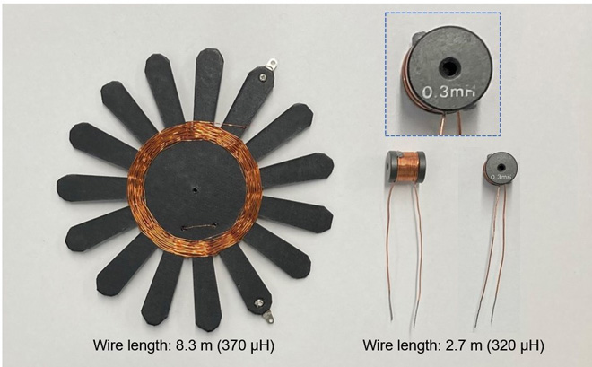
Figure 6. Comparison of a spiderweb inductor and an inductor wound on a core
Furthermore, when enameled wire of the same length as that wound on the spiderweb inductor was tightly wound on a 120 mm ferrite rod, the inductance was 2 mH. It is clear that the function of the ferrite core is very large.
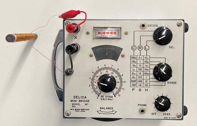
Figure 7. Measurement of inductance on a ferrite rod inductor
Investigation - Part 3 (What happens to inductance when wound on a toroidal core?)
As you can imagine, the inductor inductance with a ferrite core is much higher than that of an inductor with an air-core inductor. Now, let's see what happens if I wind the same length of enameled wire around the toroidal core.
When I wound 8.3 m of enameled wire with a diameter of 0.321 mm around the toroidal core, I could wind 194 turns. When I measured the inductance of this inductor using the impedance bridge, it was 42 mH. This is 20 times greater than the inductance when wound on a ferrite rod. The power of the core is tremendous.
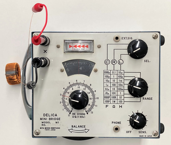
Figure 8. Measurement of inductor wound on a toroidal core
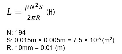
The self-inductance of an inductor wound on a toroidal core, can be calculated by the formula below. I cannot calculate it with certainty because I do not have the exact data of permeability, but if I assume ┬Ą=10x10-4, it will be about 45 mH. Although this is only a provisional data, the inductance is almost equal to the actual measured value.
Used a web-site http://ipsylon.jp/2016/05/16/crystal-set-parts8/ as a reference for making the spiderweb inductor mount.
Technical Trivia by Dr. FBŃĆĆbacknumber
- Generating ŌĆ£Sawtooth WavesŌĆØ using a D/A conversion circuit and a counter IC
- Examining a D/A converter using a Resistor Ladder
- Electronic firefly and its circuit description
- Controlling the rotation speed of a DC motor
- Description of up-down counter using 74HC192 and 74HC4511 ICs
- Considerations when making a dual voltage power supply for operational amplifiers
- Observing filter characteristics with a white noise generator
- Is noise actually reduced in twisted pair cables?
- Experiments on divider circuits using a 74HC74
- Consideration of using a photocoupler as a voltage-variable resistor
- Distorted waveform spectrum as observed on a tinySA
- Trial making of a QFH antenna
- About the inductance of coils
- Operation of analog switches
- Small digital voltmeter, 2-wire type / 3-wire type. What is the difference?
- Constant current circuit using an Op-Amp
- Coaxial cable loss to UHF and SHF
- 2.4 GHz Wireless LAN Antenna
- Let’s use MOSFETS
- 25th Comparator
- The principle of PLL
- Examination of the MLA performance
- About the Fresnel zone of the SHF band
- Level difference under open and load ends of an SSG
- Is “Made in Japan” alive? (UHF adapter again)
- Possibility experiment of passive repeater with the Back-to-Back antenna
- Why you should make SWR measurements just below the antenna!
- How reliable is the L-type BNC?
- Is the Bird 43 accurate enough?
- Does a wire dipole antenna need a balun?
- Why we donŌĆÖt use a silicon diode in a crystal radio?
- How to light the 7-segment LED
- Measurement of Antenna Performance on Handheld Transceivers (Part 3)
- Measurement of Antenna SWR on Handheld transceivers (Part 2)
- Measurement of Antenna SWR on Handheld transceivers(Part 1)
- An SWR meter
- V/UHF 3-Band Antenna Dismantling Note