


Technical Trivia by Dr. FB
How reliable is the L-type BNC?

Dr. FB
The IC-705 has a special LC-192 multi-bag sold as a separate option. If you attach the BNC L-type connector to the IC-705 and put it in the LC-192 as it is, you can attach the antenna without a coaxial cable while keeping the IC-705 in the bag, which is very convenient to operate. For this reason, a BNC L-type connector is a “must-have” item.
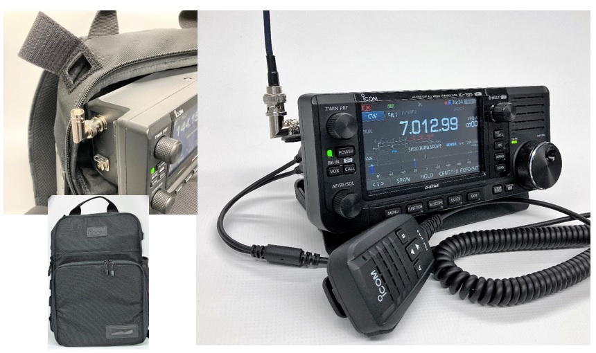
However, I heard from a ham friend that using an L-type connector reduces the reception sensitivity. If you replace it with another connector, you can receive without problems, so it is certainly not a problem with the IC-705 itself. It's hard to believe, but there seems to be a problem with the L-type connector. If the connector is used for a long time, the center pin may develop a poor contact.
While thinking that way, the input and output of the L-type connector are bent 90 degrees between the ends, but I was interested to see the details of how they are connected. We can't usually see the inside of a connector, but I had a chance to see a cross section of it in a special way. Surprisingly, I realized, "If this construction is used, problems will occur. Is this the cause of poor contact?"
X-ray photo of the inside of BNC-MJ
X-rays enable viewing the inside construction without cutting. The outside material of the connector is made of metal. I wondered if the inside structure could be seen through the metal, but first Dr. FB tried to see through the material with an X-ray device. (Figure 1) I thought I couldn't see the inside structure of the metal, but the inside structure was clearly visible, as shown in the photo below. (Figure 1)
You can see that the ends of the BNC and SO-239 connectors are firmly connected through the X-ray photo. Examining this X-ray photo, if a contact failure occurs, it is only possible that the center pin has become loose by the connector being inserted and removed many times. Another problem is that the center pin on the SO-239 is not properly installed, and you can see it from the X-ray photo that it is not installed straight. "What is this!" I'd like to be careful when purchasing, but since you can't see the inside from the outside, you can only take your chances.

Figure 1 The center pin on the SO-239 is at an angle.
Cut the conversion connector of BNC-P SO-239 with a metal saw
I cut it with a metal saw to see the inside construction of the connector seen in Figure 1. (Figure 2) By cutting it, I understood the construction inside. You can't see the whole interior clearly in the photo, but you can see it by shining a light on the gap.
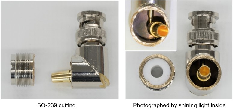
Figure 2 Connector cutting with a metal saw
With the conversion connectors shown in Figures 1 and 2, there was a problem with the mounting accuracy of the SO-239 end as you can see, but the connection between both ends seem to be firmly connected internally, but there is a possibility of poor contact. Therefore, I investigated another L-shaped conversion connector in the same way.
The connector cut with a metal saw
Figure 3-1 (left) is an X-ray photo. If you look closely at the part circled in yellow, it seems that both conductors at the BNC-J and BNC-P ends are not touching the part that is bent 90 degrees. This was also cut with a metal saw because it was not clear on the X-ray. This L-type connector has one BNC-J (jack) end and one BNC-P (Plug) end.
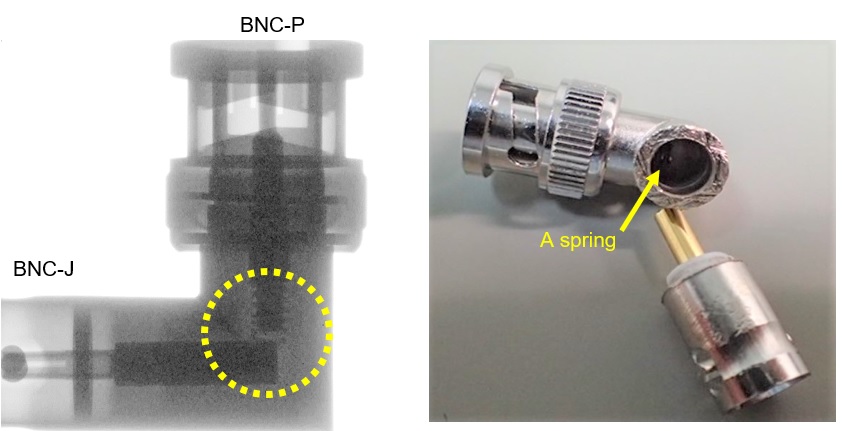
Figure 3-1 L-type BNC-P BNC-J connector
In Figure 3-1, if you look at the photo of the cut on the right side, you can see something like a spring inside. Figure 3-2 is a magnified shot taken by shining light from another angle. Obviously, it is a spring. A spring is used at the point where the conductors connect at 90 degrees. At the point where this spring and the conductor of BNC-J bend at 90 degrees, they are brought into contact and joined. As expected, Dr. FB is surprised. In this case, it is no wonder that poor contact occurs.
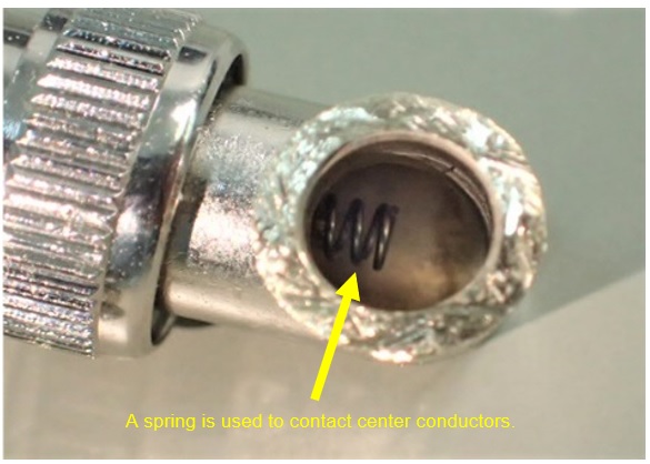
Figure 3-2 A spring is used at the joint.
Introducing a new weapon to see inside
At this point, I became strongly motivated to see the complete cross section of the connector. While exploring various ways to do this, I found a new weapon. This machine is used to inspect materials such as mechanical parts. (Figure 4)
In this machine, the material to be inspected is hardened with resin and then scraped with a rotating abrasive. Figure 5 shows a cross section taken with this machine. You can see the cross section very clearly.
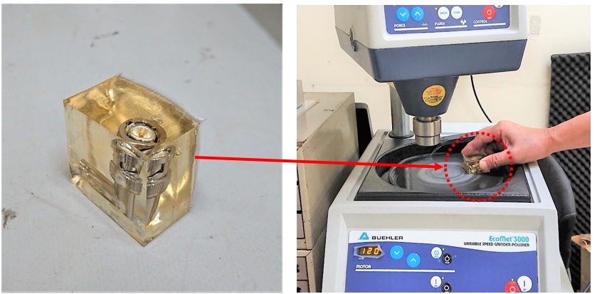
Figure 4 (Left)Harden the connector to be examined. (Right)Polishing the cross section.
We have prepared three types of BNC L-type connectors that are different in appearance. (Figure 5)
Connectors (A) and (B) were purchased from a major online shopping site. They cost 1,380 yen (approximately 13 US dollars) including shipping for 5 pieces. The connectors were sent from Hong Kong to Osaka Japan. If the shipping fee is approximately 5 dollars, the unit price of the connector is about a 1 dollar and 70 cents. Calculating from that price, I think the unit cost is 50 cents or less.
Connector (C) was bought at a store that was at a ham event. The price for each is about 3 dollars per piece. You wouldn't even imagine that the inside of the connector is constructed to cause poor contact. If one L-type BNC connector costs 3 dollars, I think that many amateur radio operators have purchased it.
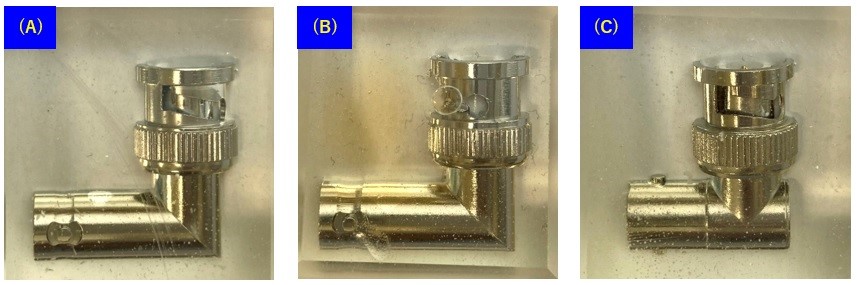
The three photos in this row are flipped left and right to match the direction of the photo below.
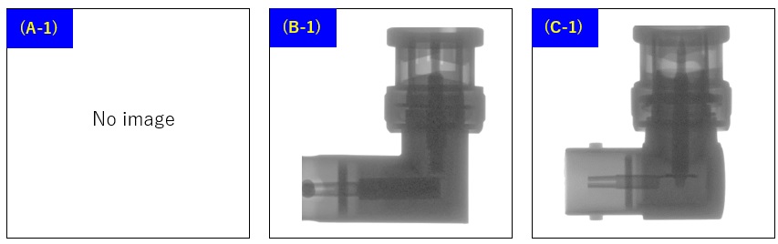
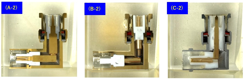
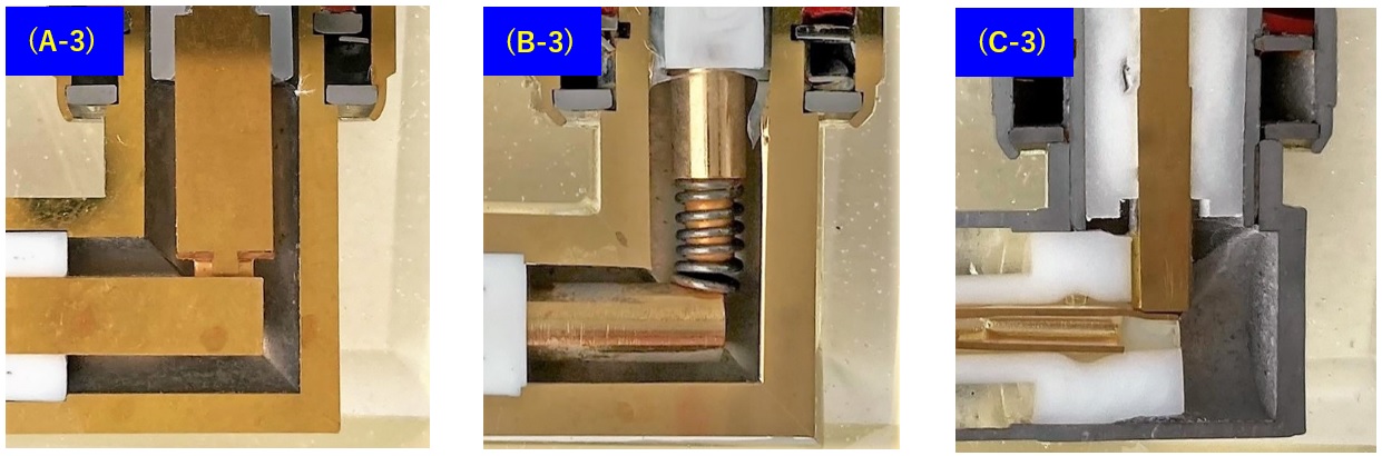
Figure 5 Three different types of inside joint construction
Consideration of the cross section of the BNC L-type connectors
Looking at the cross section of these connectors, there are two points to be concerned about. One is the connection method and the possibility of poor contact at the part that bends 90 degrees inside the connector, as mentioned at the beginning. The other one is the characteristic impedance of the BNC connector. I will explain each point of concern below.
(1) Possibility of poor contact inside the connector
Looking at photos A-2 to C-2 in Figure 5, you can see that all manufacturers are struggling with the construction of the part that bends at 90 degrees. All have different construction, but all appear that they can cause poor contact, and looking inside will not eliminate your anxiety. It is a part that can never be used for precision measurements.
Above all, if you look at the photos B-2 and B-3, the contacts are used with a spring. If you zoom in on B-3 further, you can see that the spring is already rusted and the rust is attached to the center pin of the BNC. (Figure 6)
From the color of the photo, the spring does not seem to be gold-plated, and so is very likely a poor contact. This may be the cause of the decrease in reception sensitivity due to poor contact of the L-type connector.
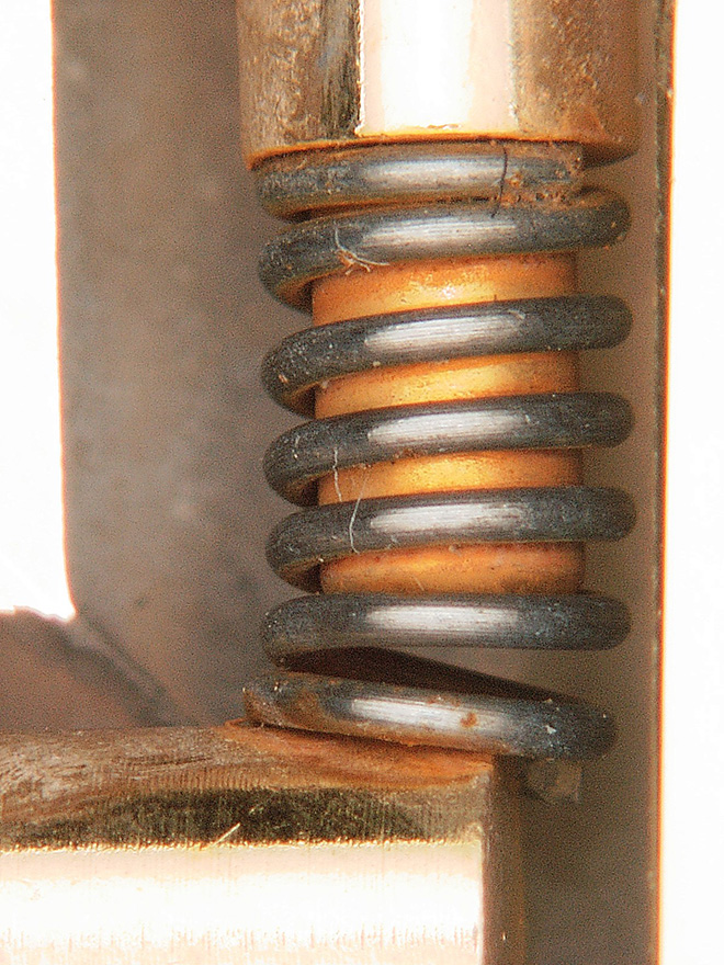
Figure 6 Enlarged view of B-3 photo (The spring is rusted)
In addition, regarding the (A) and (C) connectors, the input and output tips are not securely soldered or brazed with copper wire, so the possibility of poor contact remains.
(2) Characteristic impedance of the connector
We amateurs pay attention to transmission line loss, especially when operating in frequencies above the UHF band. Therefore, for example, BNC or Type-N connector is used for impedance matching between a radio and a coaxial cable and the antenna, and the characteristic impedance of the transmission line including the coaxial cable is kept at 50 Ω. I was able to see the cross section of the BNC connector this time. The appearance is in the form of BNC connectors used in 50 Ω transmission lines, but the internal structure makes it tempting to doubt that these BNC connectors are really 50 Ω.
Figure 7 shows the formula for calculating the characteristic impedance of the coaxial cable from the inner and outer diameters of the outer and inner conductors. I honestly do not know which one is a correct BNC, and which one is not 50 Ω. The inside construction is that the input and output points only need to be connected with a piece of wire. VHF and UHF are not considered at all in these BNC connectors.
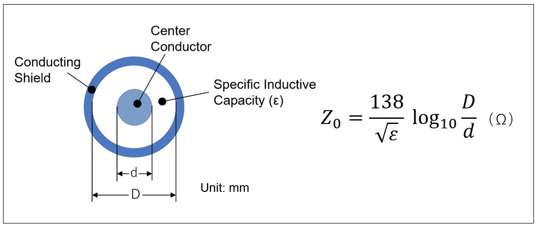
Figure 7 Formula for the characteristic impedance of coaxial cable
Summary
The electrical and mechanical specifications of the BNC connector are defined as standards by public institutions such as JIS, IEC, and MIL. Originally, the characteristics were guaranteed, but if the price is around 3 dollars per piece, it seems that you would give up getting the precision BNC connectors. I would like to see a BNC L-type connector that meets or exceeds specifications.
Even with the BNC connector, the straight type seems to have the input and output ends firmly connected by a conductor instead of such a point contact. Regardless of the BNC connector, it seems that you need to be especially careful when joining with L-type connectors.
Supplementary information
Another BNC L-type connector cross-section information was available. (Figure 8) I was even more surprised to see these photos.
If you use a BNC L-type connector and feel that the reception sensitivity has decreased, you should first suspect the BNC connector, not the radio.
FBDX
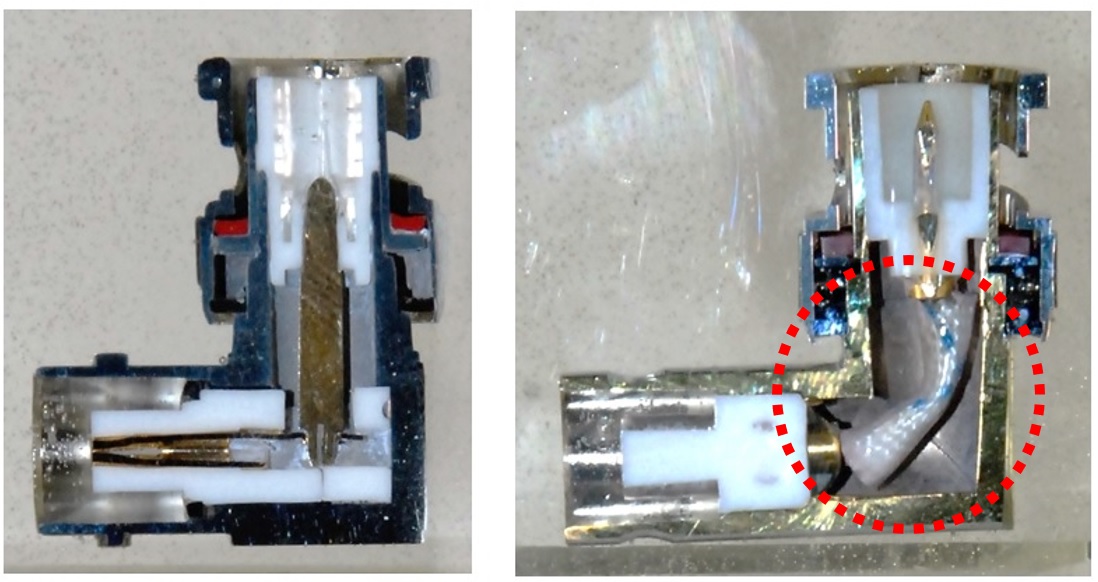
Figure 8 The connector to the right has an insulated tube inserted.
Technical Trivia by Dr. FB backnumber
- Generating “Sawtooth Waves” using a D/A conversion circuit and a counter IC
- Examining a D/A converter using a Resistor Ladder
- Electronic firefly and its circuit description
- Controlling the rotation speed of a DC motor
- Description of up-down counter using 74HC192 and 74HC4511 ICs
- Considerations when making a dual voltage power supply for operational amplifiers
- Observing filter characteristics with a white noise generator
- Is noise actually reduced in twisted pair cables?
- Experiments on divider circuits using a 74HC74
- Consideration of using a photocoupler as a voltage-variable resistor
- Distorted waveform spectrum as observed on a tinySA
- Trial making of a QFH antenna
- About the inductance of coils
- Operation of analog switches
- Small digital voltmeter, 2-wire type / 3-wire type. What is the difference?
- Constant current circuit using an Op-Amp
- Coaxial cable loss to UHF and SHF
- 2.4 GHz Wireless LAN Antenna
- Let’s use MOSFETS
- 25th Comparator
- The principle of PLL
- Examination of the MLA performance
- About the Fresnel zone of the SHF band
- Level difference under open and load ends of an SSG
- Is “Made in Japan” alive? (UHF adapter again)
- Possibility experiment of passive repeater with the Back-to-Back antenna
- Why you should make SWR measurements just below the antenna!
- How reliable is the L-type BNC?
- Is the Bird 43 accurate enough?
- Does a wire dipole antenna need a balun?
- Why we don’t use a silicon diode in a crystal radio?
- How to light the 7-segment LED
- Measurement of Antenna Performance on Handheld Transceivers (Part 3)
- Measurement of Antenna SWR on Handheld transceivers (Part 2)
- Measurement of Antenna SWR on Handheld transceivers(Part 1)
- An SWR meter
- V/UHF 3-Band Antenna Dismantling Note