


Short Break
Building of an RF Volt-Ammeter for QRP operation
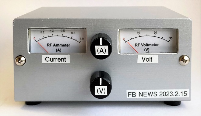
Completed the RF Volt-Ammeter
The RF Volt-Ammeter is inserted into the transmission line (coaxial cable) between a transceiver and an antenna. It is a measuring instrument used to check the state of the load (antenna) during transmission by monitoring the voltage in the transmission line and the RF current flowing through it. If the voltage and current are known, the transmission output can be obtained by a formula of P=I×E. This meter can also be used as a simple power meter.
The IC-705’s transmit power is adjustable in a percentage.
The Icom IC-705 has a multi-function knob on the front panel to adjust the output power in 1% steps, with 10 W of full power as 100 %. When 13.8 V DC is supplied to the IC-705 with an external power supply, the IC-705 produces a maximum output of 10 W. If this output adjustment control knob is set to 50 %, the output will be 5 W. If it is set to 30 %, the output will be 3 W. This percentage output adjustment is reasonably accurate. Even without a power meter, if you trust this adjustment knob, you will get an approximate output with the percentage figure.
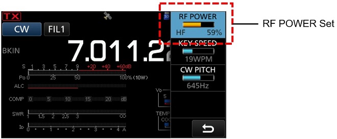
Figure 1. Screen of the IC-705 output adjustment
Find the transmit power using P=I×E
The transmit power (P) can be obtained from the voltage (E) generated at both ends of the load (Z) and the current (I) flowing through the load using the formula P = I×E. I tried to find out if this could be used to determine the transmit power. When a 10 W output is applied to an impedance (Z) of 50 Ω load, I found that a voltage of 22.4 V is produced at both ends of the impedance Z. The current flowing in the transmission was found to be 0.45 A from Ohm's law of I = E/Z.
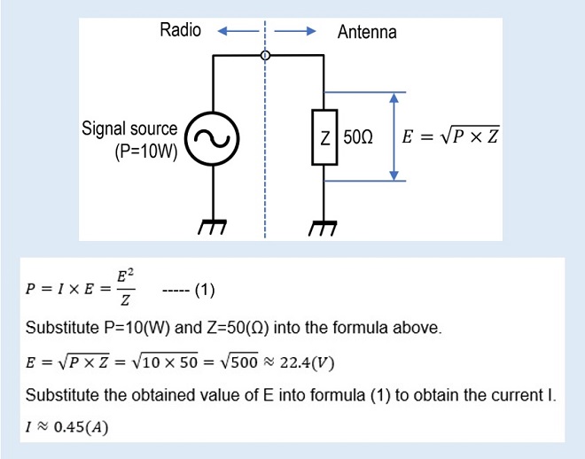
Figure 2. Calculation of the voltage produced at both ends of the load and the current flowing in the transmission line.
When 10 W is output from a transmitter, the voltage at both ends of the load is approximately 22.4 V, and the current flow is approximately 0.45 A, as described above. These voltage and current values are defined as 10 W. Put another way, it means that the voltage and current generated when the IC-705 is operated at 13.8 V DC and set to 100 % output should be set (calibrated) to 22.4 V and 0.45 A respectively for each meter.
About the RF Volt-Ammeter
The RF Volt-Ammeter that I built does not represent the absolute values of the voltage and current in the transmission line. Therefore, even if the transmit power is obtained from the indicated value of the completed RF Volt-Ammeter, it should be noted from the outset that the indication is not the absolute accuracy of the transmission power in the real world. Please understand that the meter is a relative meter calibrated on the assumption that the output of the IC-705 is 10 W when 13.8 V DC is used.
(1) RF Voltmeter
A multimeter we normally use has ranges for measuring alternating current (AC). Unfortunately, voltages and currents of RF signals cannot be measured with the multimeter measuring range, even though the RF signals are also alternating currents, because the frequency is very high. The multimeter can be used from 50 Hz, the frequency of the commercial power supply in each home, up to at most the audio frequency of 50 kHz.
However, if an RF probe consisting of several components, as shown in Figure 1, is connected to a voltmeter, the relative RF voltage can be read with a voltmeter. This RF probe, shown in Figure 3, is called a P-type electronic voltmeter. These days, digital oscilloscopes that can measure up to about 50 MHz can be purchased for few thousand dollars. However, in the past, RF voltmeters with RF probes were used to design and repair transmission circuits. A voltage indicated by an RF voltmeter is a relative values rather than an absolute values, but it is very useful for designing and repairing the amplification stage of a transmitter. The high-frequency voltmeter we have built uses this principle.
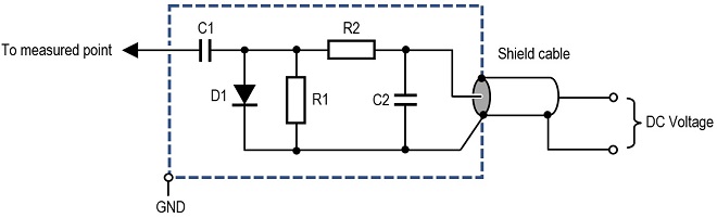
Figure 3. Principle diagram of an RF probe
(2) RF Ammeter
The current values can be known with an ammeter connected in series to the circuit. However, this principle can only be used for direct current (DC), and a little ingenuity is required when it comes to alternating current. In this RF ammeter, for example, even if a common moving coil type ammeter is inserted in series with the RF transmission line, it will not function as an ammeter because the inductance of the coil has a large impedance to the RF signals.
For this article, I made an RF ammeter by applying the circuit of an SWR meter, which has recently been incorporated in many radios. The key component is the toroidal core (TR1) shown in Figure 4. The toroidal core is used to make an RF transformer. An RF current is passed through the primary winding of the toroidal core, and the RF voltage generated in the secondary winding is detected and made to move the meter to produce an RF amp reading. The principal diagram is shown in Figure 4.
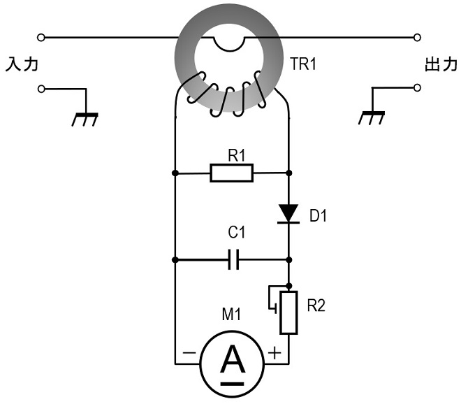
Figure 4. Principle diagram of the RF ammeter
Transformer TR1 is commonly referred to as a Current Transformer. The primary winding is simply a coaxial cable passed through a toroidal core. The primary and secondary are magnetically coupled through the toroidal core, so if the secondary is wound N times the primary, N times as much current will flow in the secondary coil as in the primary.
Schematic diagram of the RF Volt-Ammeter
Figure 5 shows the schematic diagram of the RF Volt-Ammeter made with reference to Figures 3 and 4 above. For individual components shown in the schematic diagram, a few explanations will be given for the important ones.
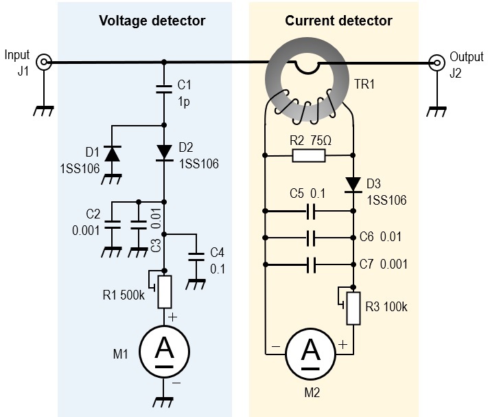
(1) C1
A portion of the RF current flowing in the center conductor of the coaxial cable is extracted by C1, which is then detected and used to swing the meter. First of all, C1 had a value of 1 pF, but the capacitance was a little too small and the meter did not swing full scale. If the meter is replaced with a more sensitive meter, or the coupling capacitor's capacitance is increased from 1 pF to 2 pF or larger, for example, the meter will swing to full scale, but increasing the capacitance of the capacitor will also lead to SWR deterioration. The final capacitance of the coupling capacitor was set to 1 pF because the SWR is not affected if the capacitance of the coupling capacitor is as small as possible. In reality, however, a little more solder was put on the soldering area on the back side of the PCB to increase the coupling capacitance.
(2) D1~D3
Diodes D1 to D3 detect RF signals to convert them to direct current (DC). In principle, almost any diode can be used to detect RF signals and convert them to DC signals. However, since the diode extracts a weak signal to swing the meter, a Schottky barrier diode with as lowest possible forward voltage (VF) should be used. You can also use 1N60 Germanium diodes familiar from germanium radios.
(3) M1, M2
Meters M1 and M2 used in this project are shown in Figure 6. These meters come in a plastic case like those used in radios or FM tuners. The full scale of the meter used is measured to be current of 0.5 mA. Both M1 and M2 are marked with the symbol (A) in the schematic diagram because they are used as ammeters. If you use a voltmeter for M1, the meter will not work. M1 uses the current value as a voltmeter.
The cover and dial of this meter were carefully removed and replaced with a meter plate created on a PC. A sample meter plate is shown in Figure 7. Click to enlarge and print it out on your printer according to the meter to be used.
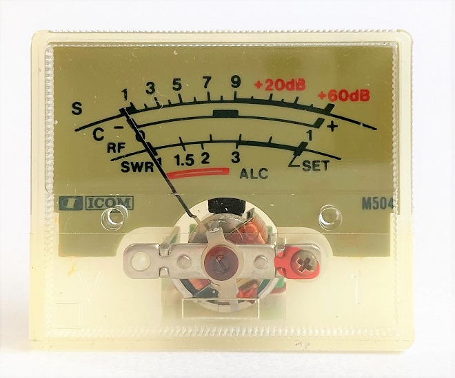
Figure 6. Full-scale 0.5 mA indicator used as a voltmeter and ammeter
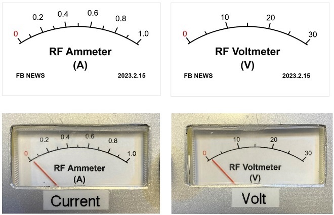 Figure 7. Sample of dial (Click to enlarge.)
(4) TR1
Wind the coil on a toroidal core, as shown in Figure 8. Ten turns of φ0.3 mm Polyurethane copper wire are uniformly wound on the core. The outside diameter of the toroidal core used was φ15 mm. I don't know the component name or permeability of the toroidal core, but in my experience, if it is a toroidal core, it will work appropriately. The output voltage and current vary, depending on the magnetic permeability, but this can be adjusted by R1 and R3 adjustment pots connected in series with meters.
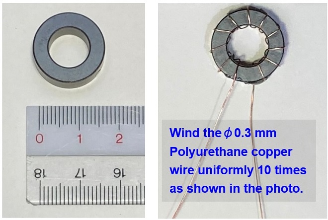
Figure 8. Current transformer wound on a toroidal core (TR1)
Building
Most of the circuit components are mounted on the universal board. The meters and adjusting control pots R1 and R3 are mounted on the front panel and the input/output connectors J1 and J2 are mounted on the rear panel. The current transformer TR1, shown in Figure 8, is fixed with adhesive to the processed board (PCB), as shown in Figure 9. Figure 10 shows the completed PCB assembled into the case.
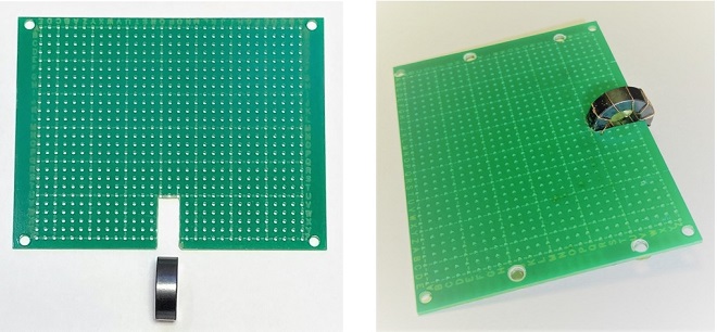
Figure 9. Mounting the current transformer on the PCB
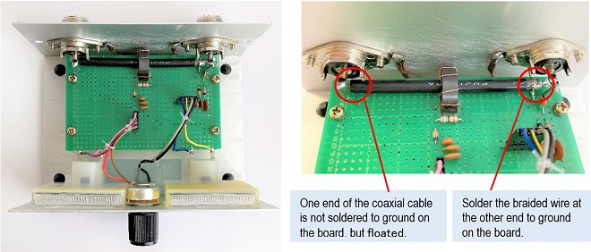 Figure 10. Inside view (Click to enlarge.)
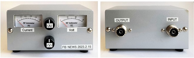
Figure 11. The completed RF Volt-Ammeter
Adjustment
As mentioned above, the completed RF Volt-Ammeter is calibrated with a transmitter that outputs exactly 10 W to calibrate the meter. This time, an Icom IC-705 is used as the 10 W transmitter, and the 50 Ω dummy load are connected to the input and output connectors, respectively, as shown in Figure 12.
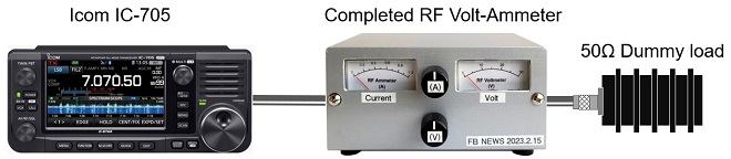
Figure 12. Calibration of the meter
Apply 13.8 V DC to the IC-705 to make it ready for 10 W operation. The IC-705 should be set on any desired HF band up to 28 MHz. Set the IC-705 to RTTY and push PTT on the microphone to transmit 10 W carrier waves. Adjust the multi-function knob on the IC-705 to show 100 % on the RF POWER scale, as shown in Figure 1. Adjust the Voltage control knob (V) on the front panel to show 22.4 V on the Volt meter, at 10 W output. Then adjust the ammeter control knob (A) to show a current value of 0.45 A on the Ammeter. The product of 22.4 V and 0.45 A is 10 W. If the load condition changes, the current value will change, indicating that an abnormality has occurred.
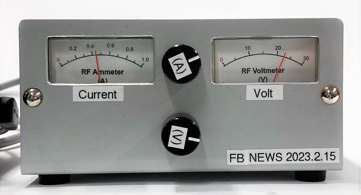
Figure 13. Set the meter indications for 22.4 V and 0.45 A
Consideration
In the actual operation test, the SWR did not deteriorate much from 1.9 to 28 MHz, and the results were not so bad. At 50 MHz, the SWR increased to about 1.5 simply by connecting this meter. The SWR deteriorated significantly on 144 MHz and above, and the meter I made was useless. This meter is inserted between the transceiver and the antenna, so it becomes part of the transmission line. At higher frequencies, the insertion of this meter adversely affects the impedance of the transmission line.
When testing with a 50 Ω dummy load connected to the meter, I did not have to adjust the front panel control pots when changing bands, but in actual operation, even if I calibrated the voltage and current on one band, I would have to calibrate the voltage and current again when QSYing to another band. This is because the impedance of the antenna is not always 50 Ω relative to the frequency.
I also found that radio waves were radiated inside the case on 144 MHz and above, which affected the circuitry and resulted in abnormal voltage and current readings. Experiments confirmed that this phenomenon could be reduced by shielding the circuit with a copper plate, or similar material, after detecting high frequencies. This time, I was not able to correct the problem to that extent, but if I have another opportunity, I would like to make it possible to use it at least up to 144 MHz.
CL
CQ Publishing Co., Ltd. CQ Publishing Co., Ltd. CQ Publishing Co., Ltd.
CQ Publishing Co., Ltd.
上級ハムになる本
Advanced Ham Radio Handbook
作りながら学ぶ初めての高周波回路
Building and Learning for the First Time High-Frequency Circuit
エレクトロニクス製作アイデア集[3]]
Electronics Project [Vol. 3]
トロイダルコア活用百科
Toroidal Core Application Encyclopedia
Short Break backnumber
- How many colors do you see when a colored disc is rotated at high speed?
- Making a dual Positive/Negative voltage power supply in a single box, for experiments
- Building of an RF Volt-Ammeter for QRP operation
- White noise generator project
- One day electronics project – Making a simple antenna tuner for QRP operations
- Can the RHM12 portable antenna be matched with a bicycle body on HF?
- Making an “ON AIR” lamp using LM358
- Making a simple anemometer
- Making a sound machine say “Good morning. Thank you for everything.”
- Electronics project for the 10 MHz reference signal generator (2)
- Electronics project for the 10 MHz reference signal generator (1)
- Making a straight type AM radio using a TA7642 IC
- About splitters
- Electronics project for FB NEWS: Making a decoration light string
- Making a Simple Electric Field Strength Meter
- Building a simple QRP power meter
- Building a 20 Amp electronic DC load device using an N-channel MOSFET for the load
- Building an automatic backup power switching unit
- Overvoltage protection device using LM358: Part 2
- Building an Over Voltage Protector: Part 1
- Making a 50 MHz monoband MLA without a variable capacitor
- Making a 50 MHz monoband MLA.
- Let's connect a computer headset to the IC-705
- Building a microphone selector
- Building an audio amplifier using an LM386 IC chip
- An External Keypad for Icom Transceivers
- After all, is the receiver good for Up-conversion?
- Find the gain of the stack antenna
- The mystery of controlling the microphone and PTT with only two wires
- RFID tag