


Short Break
An External Keypad for Icom Transceivers
Some Icom transceivers have a function called “External Keypad.” This is a convenient function to select memories, such as CW messages, SSB/AM/FM voices, and RTTY and PSK messages with a homemade keypad connected externally.
Some amateurs are reluctant to make something themselves, but the only necessary parts are switches, resistors, plugs, jacks, a few cables, screws and a case. All you have to do is simple case building, parts mounting, and soldering. No power supply is required.
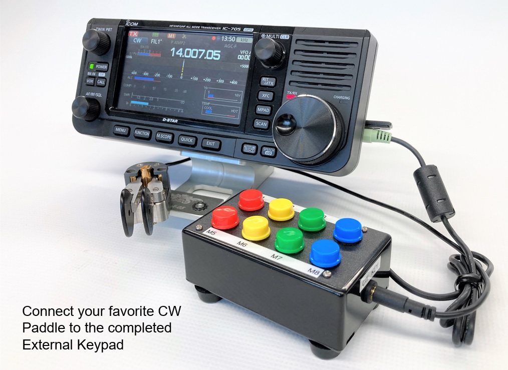
Figure 1. The completed external keypad
What is the function of the External Keypad keys?
Icom transceivers have 4 or 8 memories, depending on the model, in which the messages you want to send are stored. CW, SSB/AM/FM voice, and RTTY and PSK messages can be stored in those memories, and the contents can be sent by pushing the memory switch. Therefore, it is a convenient function for contests and portable operations.
Let's take a look at the circuit diagram
This time, we will build an external keypad exclusively for the IC-705. The circuit diagram is shown in Figure 2. below. Please refer to the "Connector Information" page of the IC-705 instruction manual for this circuit diagram and its operation.

Figure 2. Circuit diagram of the external keypad from the instruction manual of Icom IC-705
Let’s arrange the parts
Figure 3. below shows the necessary parts, as shown in the circuit diagram. The circuit is composed of switches S1 to S8. The required switches are called "momentary switch," which turns ON only when pushed and returns to OFF when released.
The external keypad also has a jack for the CW paddle so that you can use it with your usual CW paddle.

Figure 3. Parts list
Building the external keypad
Assuming that the IC-705 will be used in the field, I chose the smallest possible case so that it would not be bulky to carry. Also, I chose a switch with a large button so that you can easily see the switch number and activate it with the touch of your finger. In addition, the switch is physically strong, considering that it is used a lot in calls such as pile-ups, as you push the button many times.
If you print M1 to M8 on the completed external keypad with a lettering sticker, it will be even cooler!

Figure 4. Parts are installed on the universal board.

Figure 5. Completed external keypad
Turn ON the external keypad function in the IC-705 settings
Before you insert the stereo plug of the external keypad into the key jack of the IC-705, you need to select “External Keypad" in the SET mode in the IC-705. The following is an excerpt of the contents described in the IC-705 instruction manual.
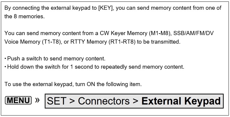
Figure 6. How to set IC-705 required when connecting an external keypad
You can also connect your usual CW paddle to the jack on the side of the keypad case.
CL
Short Break backnumber
- How many colors do you see when a colored disc is rotated at high speed?
- Making a dual Positive/Negative voltage power supply in a single box, for experiments
- Building of an RF Volt-Ammeter for QRP operation
- White noise generator project
- One day electronics project – Making a simple antenna tuner for QRP operations
- Can the RHM12 portable antenna be matched with a bicycle body on HF?
- Making an “ON AIR” lamp using LM358
- Making a simple anemometer
- Making a sound machine say “Good morning. Thank you for everything.”
- Electronics project for the 10 MHz reference signal generator (2)
- Electronics project for the 10 MHz reference signal generator (1)
- Making a straight type AM radio using a TA7642 IC
- About splitters
- Electronics project for FB NEWS: Making a decoration light string
- Making a Simple Electric Field Strength Meter
- Building a simple QRP power meter
- Building a 20 Amp electronic DC load device using an N-channel MOSFET for the load
- Building an automatic backup power switching unit
- Overvoltage protection device using LM358: Part 2
- Building an Over Voltage Protector: Part 1
- Making a 50 MHz monoband MLA without a variable capacitor
- Making a 50 MHz monoband MLA.
- Let's connect a computer headset to the IC-705
- Building a microphone selector
- Building an audio amplifier using an LM386 IC chip
- An External Keypad for Icom Transceivers
- After all, is the receiver good for Up-conversion?
- Find the gain of the stack antenna
- The mystery of controlling the microphone and PTT with only two wires
- RFID tag