


Short Break
After all, is the receiver good for Up-conversion?
Frequency composition of the superheterodyne technique
I think there is no doubt that more than 90% of the receivers in the market today still use the superheterodyne technique. The superheterodyne system is a system that initially converts received signals into another frequency called the ‘intermediate frequency’ (IF).
It is said that how the intermediate frequency is generated in the frequency conversion process affects the performance of the receiver. Several amateur radio manufacturers in Japan produce their own flag ship radio. Company A and Company B use the down-conversion system, with an intermediate frequency lower than the received frequency, and Company C uses an up-conversion system with an intermediate frequency much higher than the received frequency.
Figure 1 is a typical receiver frequency conversion diagram. Assuming that the received frequency is 14MHz, the local oscillation frequency (fLO) is approximately 23MHz in order to generate the first intermediate frequency (fIF) at 8-9MHz. The output of the mixer is the frequency of the sum and the difference of fR and fLO. The output of the mixer, the difference of 9MHz, is passed through a BPF (roofing filter) and used as fIF. In this frequency conversion, fIF is set lower than the received frequency fR. This method is called ‘down-conversion.’
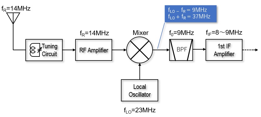
Figure. 1 An example of frequency conversion using 14MHz reception as an example (Down-conversion)
Radio waves of various frequencies arrive at the antenna. In the frequency conversion shown in Figure. 1, for example, when an undesired strong signal of 32MHz, for example, comes in from the antenna while receiving 14MHz, the tuning circuit is built in front of the RF Amplifier, but a small amount of the signal enters the mixer circuit through the tuning circuit and RF Amplifier. The mixer proceeds to output the sum and difference of 32MHz and fLO.
In other words, the addition is 32+23 = 55MHz, and the subtraction is 32-23 = 9MHz. The 55MHz signal cannot pass through the 9MHz roofing filter, but the 9MHz generated by the reception of the undesired signal passes through the roofing filter and enters the IF circuit. This is the cause of receiving an undesired 32MHz signal which is the image frequency interference (= image interference) of the superheterodyne receiver.
What happens with frequency conversions using ‘up-conversion’?
Figure 2 shows a block diagram using up-conversion frequency conversion. As explained above, consider the frequency conversion assuming that you are receiving 14MHz signals. The mixer produces the sum and difference signals of the 14MHz received signal (fR) and the LO signal (fLO), respectively.
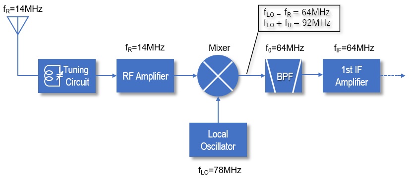
Figure. 2 An example of frequency conversion using 14MHz reception as an example (Up-conversion)
The sum, it is 14+78 or 92MHz, and the difference is 78-14 or 64MHz. The 92MHz cannot pass through the 64MHz roofing filter, but if the frequency of the difference is taken, it will pass perfectly. This is the intended result.
Even in the case of up-conversion, assuming that a 142MHz (= fR + 2 × fIF) signal passes through the tuning circuit and the RF Amplifier from the antenna and enters the mixer, the output is 64MHz (= 142-78), and it is theoretically derived that signals of the same frequency of fIF are generated. If a 142MHz signal is injected into the mixer, image interference can occur.
However, the unwanted 142MHz signal is more than twice as far away from the frequency range of HF to 50MHz and is definitely eliminated by the tuning circuit and the RF Amplifier, so the output of the mixer does not actually cause the image interference.
As you can see, eliminating the image interference needs an fIF frequency above the receive coverage frequency, that is, up-conversion. This is a major solution to eliminate image interference in superheterodyne receivers.
What is the performance of high frequency roofing filters?
Before extracting the desired signal from the signal generated by the mixer and sending it to the first IF amplifier, it is important to cut off unnecessary signals with a roofing filter. The bandwidth of the roofing filter is an important factor for this. The narrower the bandwidth, the better the selectivity with no unwanted signal passage.
The content of this roofing filter is a physical piece of crystal, and the performance and specifications are ensured by the method of cutting the crystal. Generally, lower frequencies are more advantageous for making filters with narrower bandwidths. The narrower the bandwidth, the more nearby signals can be eliminated. In other words, the down-conversion receiver can narrow the bandwidth with the roofing filter, so company A and company B have developed radios based on the down conversion method with the intention of increasing the level of RMDR (Reciprocal Mixing Dynamic Range) for adjacent signal interference.
The bandwidth of the 64MHz band roofing filter used for an up-conversion system has been realized as a surprisingly narrow band of 1.2kHz with respect to 64MHz due to the recent technological innovation of filter makers. It is no longer the narrow bandwidth only for the down-conversion system. The myth that band filtering is not realized has been solved by recent technological innovations.
The purity of the LO signal increases the selectivity
Adopting the down-conversion system, narrowing the bandwidth of the roofing filter and increasing the selectivity is a reasonable method adopted by many models. However, the image interference problem remains. When it comes to extracting only the desired frequency, the important factor regardless of whether using down-conversion or up-conversion is the purity of the LO signal.
The mixer mixes the fR and fLO signals. At this time, if the LO signal purity is poor in that the signal has a skirt like hem, the output signal of the mixer that adds or subtracts will also deteriorate, according to the LO signal purity. The basis for this is the LO signal purity shown in Figure. 3, that is the C/N (Carrier to Noise Ratio) characteristic. The C/N of the IC-7800 gradually contains noise from around -70 dB, and the signal base is expanding like a skirt. On the other hand, looking at the LO signal of IC-7850/IC-7851, even the signal around -100dB is not a signal with a wide skirt. In other words, the components of the received signal appear almost as they are in the output of the mixer.
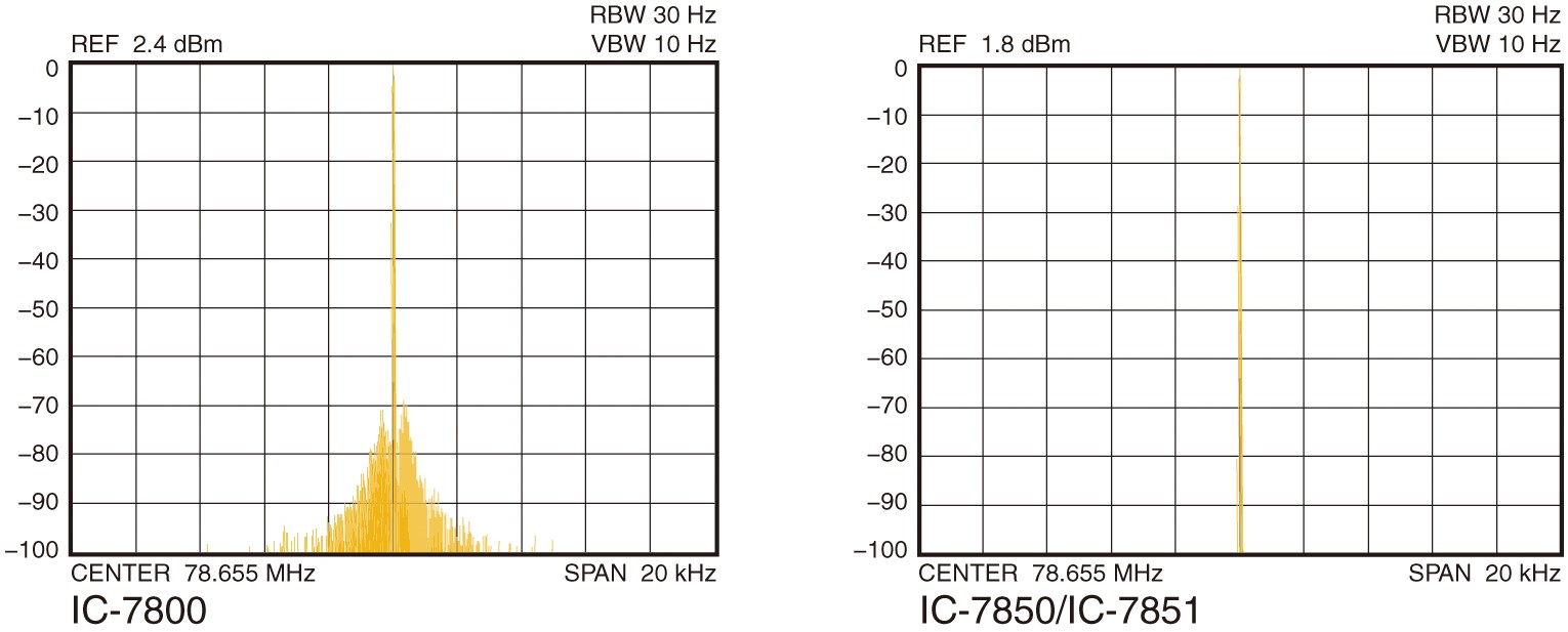
Figure. 3 Comparison of LO C/N of IC-7800 and IC-7850/IC-7851 (quoted from the Technical Reference Book of the Icom IC-7850/IC-7851)
Is the strongest in LO purity + up conversion?
One way to reduce the interference of the adjacent signal interference is to lower the IF frequency and narrow the bandwidth of the roofing filter in a down-conversion frequency configuration.
However, Company C's method uses an up-conversion configuration, which avoids image interference. Furthermore, the IF frequency is in the 64MHz range, which is very high compared to the method of companies A and B, but the selectivity is increased by the amazing narrower 1.2kHz filter.
In addition, the LO signal with greatly improved purity is used for the mixer to avoid interference of proximity signals. The previous technology, which states that HF band receivers can only ensure sufficient performance by down-conversion, has been demonstrated in company C's up-conversion radios.
CL
Short Break backnumber
- How many colors do you see when a colored disc is rotated at high speed?
- Making a dual Positive/Negative voltage power supply in a single box, for experiments
- Building of an RF Volt-Ammeter for QRP operation
- White noise generator project
- One day electronics project – Making a simple antenna tuner for QRP operations
- Can the RHM12 portable antenna be matched with a bicycle body on HF?
- Making an “ON AIR” lamp using LM358
- Making a simple anemometer
- Making a sound machine say “Good morning. Thank you for everything.”
- Electronics project for the 10 MHz reference signal generator (2)
- Electronics project for the 10 MHz reference signal generator (1)
- Making a straight type AM radio using a TA7642 IC
- About splitters
- Electronics project for FB NEWS: Making a decoration light string
- Making a Simple Electric Field Strength Meter
- Building a simple QRP power meter
- Building a 20 Amp electronic DC load device using an N-channel MOSFET for the load
- Building an automatic backup power switching unit
- Overvoltage protection device using LM358: Part 2
- Building an Over Voltage Protector: Part 1
- Making a 50 MHz monoband MLA without a variable capacitor
- Making a 50 MHz monoband MLA.
- Let's connect a computer headset to the IC-705
- Building a microphone selector
- Building an audio amplifier using an LM386 IC chip
- An External Keypad for Icom Transceivers
- After all, is the receiver good for Up-conversion?
- Find the gain of the stack antenna
- The mystery of controlling the microphone and PTT with only two wires
- RFID tag