


Short Break
Building an audio amplifier using an LM386 IC chip
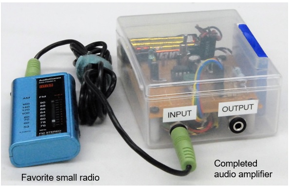
I commute to work every day while listening to NHK radio broadcasts. The radio is so small that it can be hidden when you hold it in your hand. There is no speaker in the radio, so the output is only to an earphone. You don't need a speaker for you to listen to it on your way to work, but sometimes you may want to have a speaker when you're listening to AM broadcasts while doing something else. I would like to introduce a simple audio amplifier made using an LM386 IC chip.
*Nippon Hoso Kyokai (Japan Broadcasting Corporation)
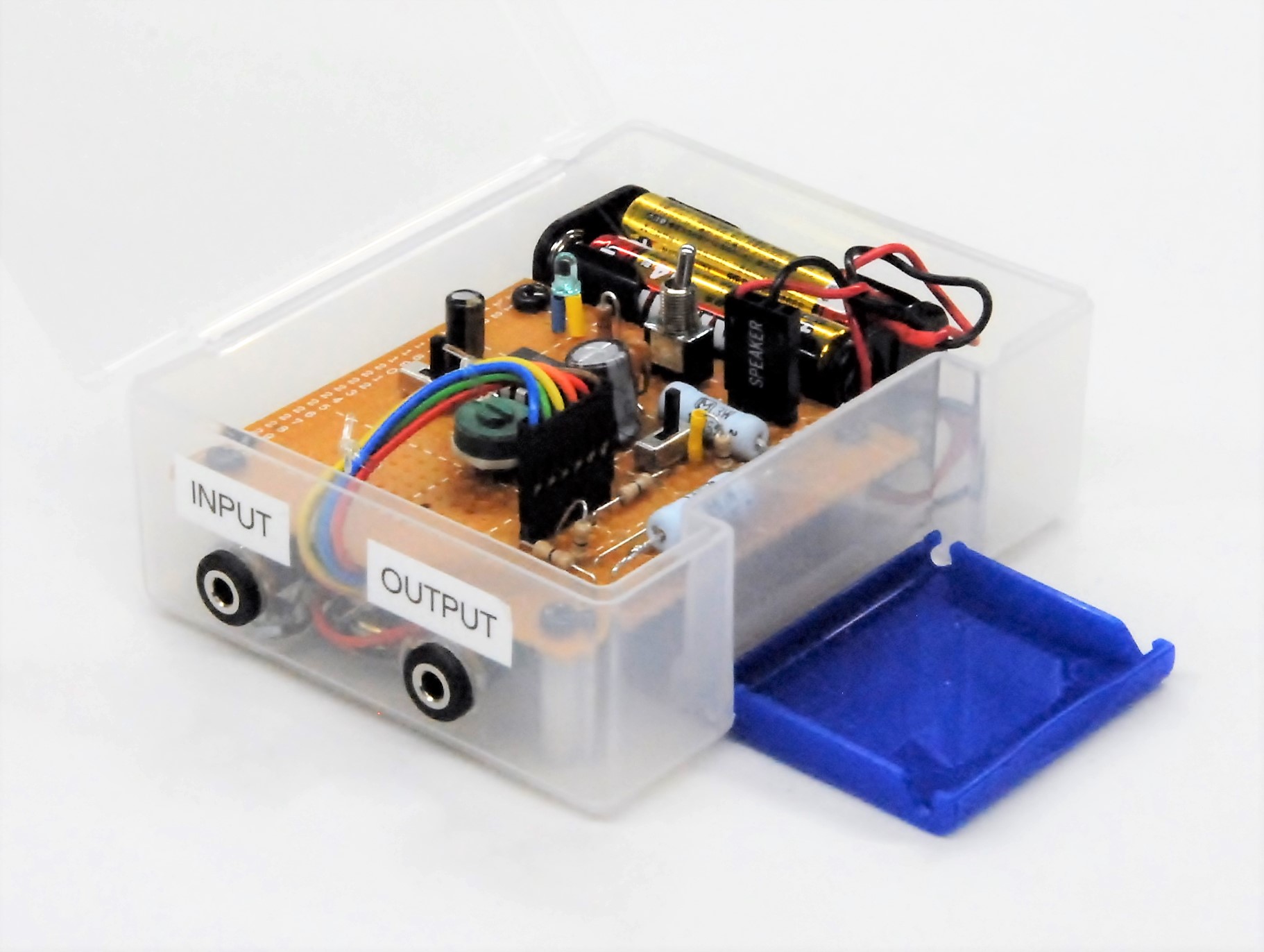
Figure 1. Complete audio amplifier using an LM386 IC chip
Determining specifications
Since the small radio operates on a single AAA battery, I aimed for a compact size that will also operate on dry batteries for the audio amplifier I made this time. I tried to make the amplifier without incurring a high cost. The case would be obtained at a Dollar Store. Install a built-in speaker of about 8Ω / 0.5W. I added a volume control that can change the output level and also gain control of the audio amplifier.
About the LM386 IC chip
According to the IC manufacturer's datasheet, the overview section explains that "This IC is a power amplifier designed for use in low voltage consumer applications, with a gain internally set to 20 for a voltage gain (=26 dB) to reduce the number of external components. However, if you want to increase the gain, by adding a resister and a capacitor externally between pins 1 and 8 you can get a voltage gain of 20 and 200 (=46 dB). This time I added an option of 20 dB gain, selectable with a switch.
My favorite specifications were the wide power range of 4V-12V, and the low current of 4mA. If this were true, it seemed that it can be driven by dry batteries. The power circuit could be omitted by driving with a dry battery. This could further reduce the number of parts. It also would have the advantage of not getting in the way by having an AC power cord in my narrow radio shack.
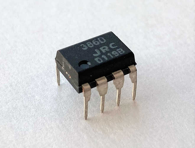
Figure 2. Appearance of LM386
Schematic diagram of the audio amplifier
Figure 3 shows the schematic diagram of the audio amplifier. This schematic uses the basic circuitry described in the LM386 data sheet. As shown in the datasheet, you can increase the gain of the IC by installing an external resistor and capacitor between pin 1 and pin 8. In this circuit, the gain is selected by SW2.
Even though the IC is energy-saving, I wanted to reduce the current consumption as much as possible because this unit operates with dry cells. Therefore, a 2kΩ resistor was connected in series to the LED that lights up when the power switch (SW1) is turned ON. With this, the current flowing through the LED is more than 2mA, which is less than 1/5 of the rating. Even with this, you can see that the blue light emitting diode is sufficiently lit.
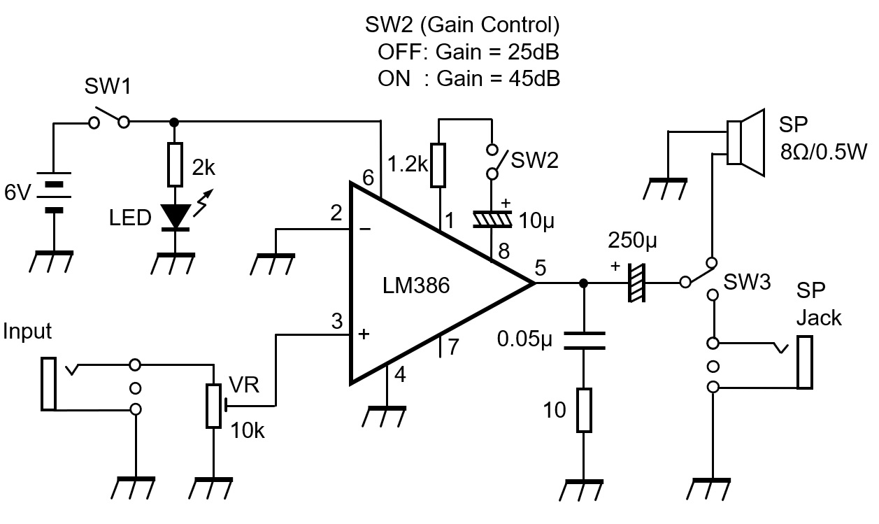
Figure 3. Circuit diagram of the audio amplifier made this time
Operation check
Set SW2 to OFF (open state) and SW3 to the SP speaker side. Connect the earphone output of the radio to the audio input jack the audio amplifier. When SW1 is turned ON, audio is heard from the amplifier’s built-in speaker. If sound is heard from the speaker, the check is complete for the time being.
Next, set SW2 to ON (closed state) while audio is coming out of the speaker. The gain switching circuit is operating normally if the audio level increases.
Checking the gain
The LM386 data sheet states that turning SW2 ON increases the gain by 20dB, so let us check it.
The confirmation was done with the WaveGene and WaveSpectra free software. WaveGene is an audio generator and WaveSpectra is an audio band spectrum analyzer. WaveGene generates a 1kHz sine wave. I observed the signal level when the signal was applied to the audio amplifier, and when it was not applied.
Figure 4 shows the level of the 1kHz sine wave generated by WaveGene and displayed by WaveSpectra. I do not know the absolute value of the input level, but that is OK because I only checked the amplification ratio of the audio amplifier. The graph shows that input level is -45 dB while the amplifier is turned OFF.
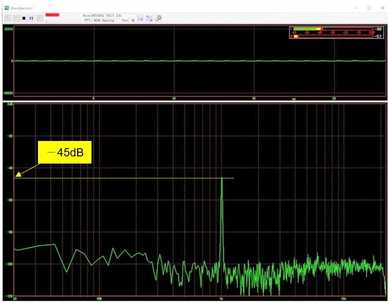
Figure 4. Signal level input to the audio amplifier
Next, I turned ON the audio amplifier, and observed the output level of the amplifier with WaveSpectra as well. The observed graph is shown in Figure 5. You can see that the output level is -20 dB. In other words, it can be seen that the difference between the level observed in Figure 4 and the level observed in Figure 5 is the gain of the audio amplifier.
Av = |-45 | - |-20 | = 25 dB
The LM386 datasheet states that "the gain is internally set to 20." Since this 20 means voltage gain, if I calculate it into dB, it becomes 26 dB. The datasheet describes voltage gain of 20 (=26 dB) but I observed a 25 dB difference in the graph. It is very close to 26 dB, so the gain of the audio amplifier is close to the datasheet value, and this is also OK.
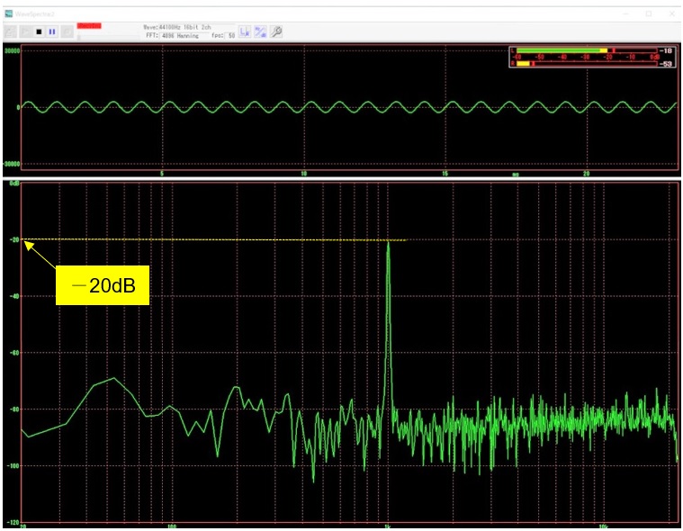
Figure 5. Audio amplifier output level (SW2: OFF)
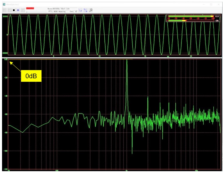
Figure 6. Audio amplifier output level with SW2 ON.
I wanted to check the frequency response characteristics, but this time I made it just to listen to AM radio with speakers, so I will end the article here.
CL
<Reference materials>
・ TEXAS INSTRUMENTS LM386 low voltage audio power amplifier datasheet
・ Welcome to efu ’s page (https://www.efu.jp.net/) WaveGene/WaveSpectra
Short Break backnumber
- How many colors do you see when a colored disc is rotated at high speed?
- Making a dual Positive/Negative voltage power supply in a single box, for experiments
- Building of an RF Volt-Ammeter for QRP operation
- White noise generator project
- One day electronics project – Making a simple antenna tuner for QRP operations
- Can the RHM12 portable antenna be matched with a bicycle body on HF?
- Making an “ON AIR” lamp using LM358
- Making a simple anemometer
- Making a sound machine say “Good morning. Thank you for everything.”
- Electronics project for the 10 MHz reference signal generator (2)
- Electronics project for the 10 MHz reference signal generator (1)
- Making a straight type AM radio using a TA7642 IC
- About splitters
- Electronics project for FB NEWS: Making a decoration light string
- Making a Simple Electric Field Strength Meter
- Building a simple QRP power meter
- Building a 20 Amp electronic DC load device using an N-channel MOSFET for the load
- Building an automatic backup power switching unit
- Overvoltage protection device using LM358: Part 2
- Building an Over Voltage Protector: Part 1
- Making a 50 MHz monoband MLA without a variable capacitor
- Making a 50 MHz monoband MLA.
- Let's connect a computer headset to the IC-705
- Building a microphone selector
- Building an audio amplifier using an LM386 IC chip
- An External Keypad for Icom Transceivers
- After all, is the receiver good for Up-conversion?
- Find the gain of the stack antenna
- The mystery of controlling the microphone and PTT with only two wires
- RFID tag