


Short Break
Electronics project for FB NEWS: Making a decoration light string

Christmas trees and packages at JR Tennoji station Osaka Japan
I would like to introduce a decoration light string this month that I made in a hurry, as I was late. The lights sold in stores have a lot of variations in the blinking of the LEDs, and they are quite well made. In addition, the blinking speed can be changed, and the lighting can be made to fade in and fade out, which is a difficult task to achieve with only discrete components. Actually, I came up with the idea that the IC that controls the LED is used in products sold at a dollar shop, so I hurriedly decided to make a simple light string. Although it is not a high-tech project, I will proceed with the building while explaining a little about the forward voltage (VF) of LEDs.
Required key components
The key components required are shown below in Figure 1.
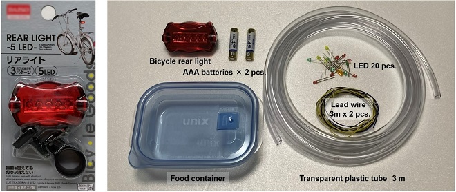
Figure 1. Rear light for bicycles (Left), Components required for building (Right)
The light shown in Figure 1 (Left) is a bicycle rear light that is sold at dollar-shop goods with a built-in key component. Recent rear bicycle lights contain several bright red LEDs. Depending on the product, the power supply seems to be 3 V from two AA or AAA batteries. A button switch is attached to the rear panel of the light, and the blinking pattern of the light changes each time the button switch is pushed. The blinking of the light used this time has 3 patterns, but it is recommended to have as many patterns as possible. When lit, you can enjoy a variety of illuminations.
Inside of the rear light
Figure 2 shows the inside of the rear light with the cover removed. The LED and the IC that controls it are mounted on the PCB (Print Circuit Board) and screwed to the case. You can remove the board by removing the screws as shown in the photo below (center). In the lower right picture of Figure 2, you can see a black circle in the center. This is the IC that controls the LEDs. I do not know what kind of IC it is because it is molded directly into the PCB with resin.
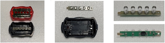
Figure 2. Inside of the rear light
Figure 3 shows a circuit diagram of the board. Five LEDs are lit with two 1.5 V batteries. When lit, it shines dazzlingly when you look directly at the LED. When I measured how much current was flowing through each LED, it was over 10mA each. With the power ON/OFF indicator installed in the electronic project, you can see that the rear light is made to emit light by passing more current than expected, considering that it is too bright if over 10 mA flows. Since 5 LEDs are mounted in parallel on this rear light, the total current can be calculated as approx. 60mA. Since the rear light of a bicycle is responsible for safe driving at night, I think it is necessary to pass this amount of current and illuminate brightly.
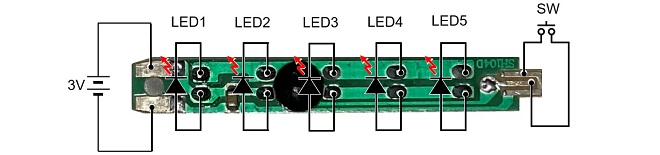
Figure 3. LED installation on the board
Measurement before modification
Before the modification, measure the voltage between the anode and cathode of each LED on the board, shown in Figure 3 above with a multimeter as shown in Figure 4. This voltage is called the diode forward voltage (VF). This rear light has a red LED installed, and when I measured the VF, it was 1.9 V.
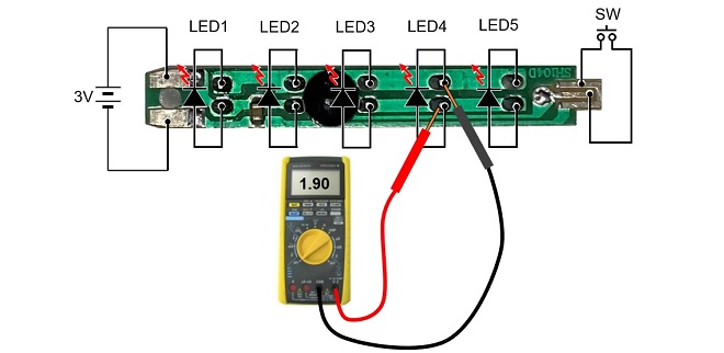
Figure 4. Measure the VF of the red LED installed in the light
When the voltage of the output of the IC was measured, as shown in Figure 6 below with all the LEDs removed, it was 3.00 V.
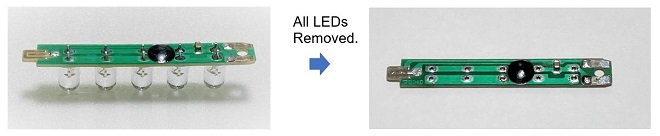
Figure 5. Remove all LEDs from the board
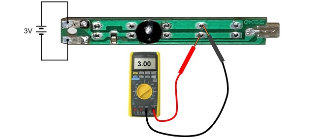
Figure 6. Measure the voltage of the output lines with all the LEDs removed.
Rear light modification
For decorative illuminations, first remove all the LEDs on the board, solder the lead wires to the output PCB lines, and install several LEDs in parallel, as shown in Figure 7. When the colorful LEDs blink, I think it is beautiful in the night light, so I installed a total of 20 LEDs in parallel on the lead wires, 6 types of blue, red, green, yellow, white, and orange, as shown in Figure 7(a).
As a result, blue and white LEDs did not light up. All other colors were lit. As shown in Figures 7(b) and (c), if only red is installed, all of them will light up even if about 20 LEDs are connected in parallel. Similarly, blue, and white LEDs were all lit when connected in a single color. Blue and white LEDs did not light up in either case when mixed connection was made, as shown in Figure 7(a). As a result, I made four types of LED light strings, without blue and white LEDs, as shown in Figure 7.
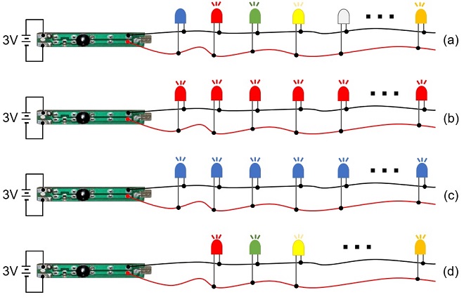
Figure 7. Examine the relationship between LED mounting and lighting
Building the decoration lights
LEDs can be installed at any interval between them, but here one is installed every 20 cm. A heat shrink tube is inserted so that the soldering of each lead wire does not short. The length is about 3 m.
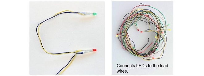
Figure 8. LED connecting on lead wires
Solder the wires attached to the LEDs to the board as shown in Figure 9(a), and then cover it with the case like the original rear light, as shown in 9(b).
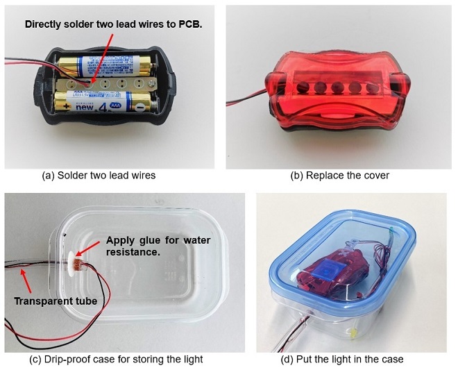
Figure 9. Assembly procedure
Finally, put the rear light in a drip-proof plastic case, insert the wired LEDs into a transparent plastic tube. You are done.
Figure 10 shows the completed decoration light string. I installed 19 LEDs. With all LEDs lit, the total current is about 30 mA. Even if the current per LED is very small, it blinks clearly and lights up when the sun goes down in the evening.
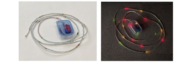
Figure 10. Decoration light string in a transparent plastic tube
Lighting verification
Figure 11 shows the results of measuring the voltage between the red and black wires with the connections shown in Figures 7(a) to (d). The voltage shown as 1.9 V or 2.8 V in the table indicates the value of the forward voltage (VF) of the diode shown in Figure 12. The VF of a silicon diode often used for switching circuits is about 0.7 V. The VF of a 1N60 diode, which is common in germanium radios, is very low, about 0.1 V. In other words, turning ON a silicon switching diode requires a voltage of 0.7 V or higher, and when the diode is turned ON, the voltage between the anode and cathode is always 0.7 V.
Schottky barrier diodes and germanium diodes are used to detect very weak radio waves because they have a low VF and allow even minute signals to pass through. However, the VF of the blue and white LEDs tested this time is as high as 2.8 V, and in the mixture of the red LED that turns on at 1.9 V and the blue LED that requires 2.8 V to turn ON, when the red LED turns ON. Since the VF will be 1.9 V, the blue LED that requires 2.8 V will not emit light because there is not enough VF to turn it ON.
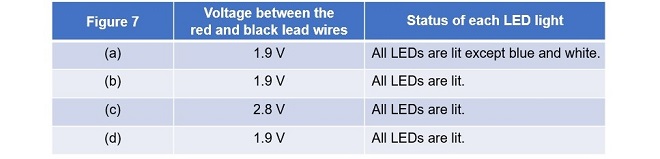
Figure 11. Voltage between red and black wires
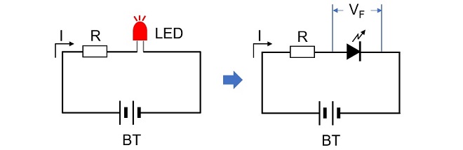
Figure 12. VF of a diode
Summary
It was a good idea to drive the LED of the decorative light strings using the IC installed in the bicycle rear light. Finally, I would like to add that I found nice decoration lights, as shown in Figure 13, when I was looking around a dollar-shop. If you are short of 19 LEDs at 3 V, there are also powerful AC powered 100 mini-bulb light strings, as shown below.

Figure 13. Found a decoration light sold at about 3 US dollars at a dollar-shop (Left)
CL
Short BreakŃĆĆbacknumber
- How many colors do you see when a colored disc is rotated at high speed?
- Making a dual Positive/Negative voltage power supply in a single box, for experiments
- Building of an RF Volt-Ammeter for QRP operation
- White noise generator project
- One day electronics project ŌĆō Making a simple antenna tuner for QRP operations
- Can the RHM12 portable antenna be matched with a bicycle body on HF?
- Making an ŌĆ£ON AIRŌĆØ lamp using LM358
- Making a simple anemometer
- Making a sound machine say ŌĆ£Good morning. Thank you for everything.ŌĆØ
- Electronics project for the 10 MHz reference signal generator (2)
- Electronics project for the 10 MHz reference signal generator (1)
- Making a straight type AM radio using a TA7642 IC
- About splitters
- Electronics project for FB NEWS: Making a decoration light string
- Making a Simple Electric Field Strength Meter
- Building a simple QRP power meter
- Building a 20 Amp electronic DC load device using an N-channel MOSFET for the load
- Building an automatic backup power switching unit
- Overvoltage protection device using LM358: Part 2
- Building an Over Voltage Protector: Part 1
- Making a 50 MHz monoband MLA without a variable capacitor
- Making a 50 MHz monoband MLA.
- Let's connect a computer headset to the IC-705
- Building a microphone selector
- Building an audio amplifier using an LM386 IC chip
- An External Keypad for Icom Transceivers
- After all, is the receiver good for Up-conversion?
- Find the gain of the stack antenna
- The mystery of controlling the microphone and PTT with only two wires
- RFID tag