


Short Break
Building an Over Voltage Protector: Part 1
Using an LM358 Op-Amp as comparator
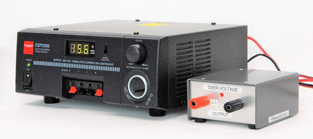
Over Voltage Protector (Right)
About two years before the new coronavirus spread worldwide, at an amateur radio event held in Osaka, there were many junk items packed with operational amplifiers (Op-Amp) such as the LM358, 4558D and 5000-series ICs. I paid 300 yen (about 3 US dollars) for them. I just bought them on impulse, which is my usual habit. The 4558D requires two power sources for V+ and V-, but the LM358 operates with a single power source, and is easy to use. So, this time I built an over voltage protector (hereafter called OVP) using that Op-Amp.
The article about building the OVP is divided into two parts. The first one uses an orthodox mechanical relay for switching to shut off the power supply, while the second one uses a semiconductor which is slightly advanced MOSFET instead of the mechanical relay.
Overview of the OVP using a relay
Figure 1 shows the configuration of the OVP. DC power is supplied to a load through the OVP device. No modification is made to the DC power supply. It is simply an external device.
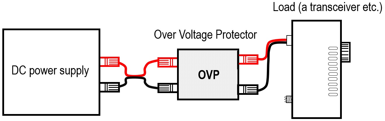
Figure 1. The OVP device between a DC power supply and a load
This OVP is a device that prevents unexpected overvoltage to the load if the output of the DC power supply exceeds the specified voltage for some reason. The device detects overvoltage using a comparator. Normally, the DC power simply passes through the OVP. But when the voltage of the DC power supply on the input side reaches around 16V, the relay turns ON and cuts off the power supply circuit.
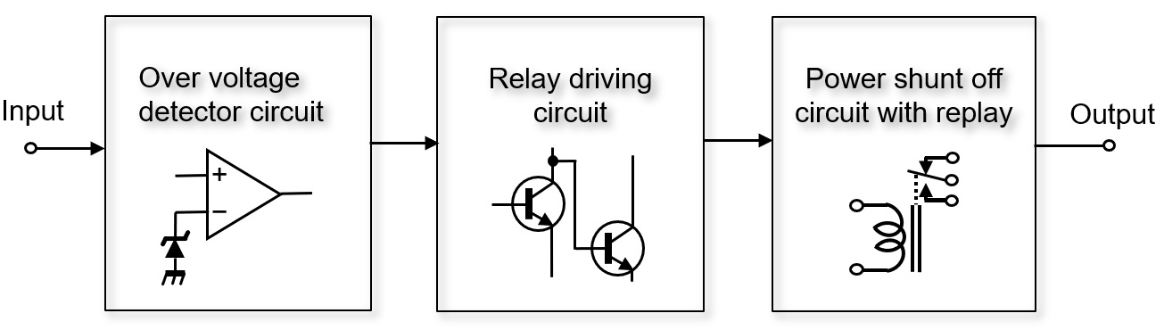
Figure 2. Configuration diagram of OVP by a comparator
Two key parts used for the OVP
Figure 3 is a circuit diagram of the OVP. There are not many parts used, and there are no special parts. The circuit operation is relatively simple.
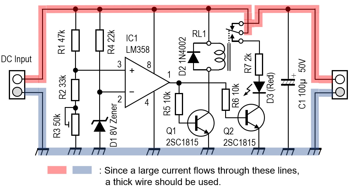
Figure 3. Circuit diagram of OVP
There are two key parts. One is the triangular part drawn in the center of the schematic diagram shown in Figure 2 above. This is the LM358 Op-Amp used as a comparator. The other is a relay with metal contacts. I selected a relay that operates at 12V DC. Since current flows through the relay contacts under normal conditions, it is necessary to select a relay according to its maximum current draw.
Circuit operation description
Figure 4 is an internal block diagram of the LM358. Two Op-Amps are included in one package. An Op-Amp operates as an amplifier when a negative feedback is applied to the amplifier. When it operates as a comparator, no negative feedback is applied.
The comparator has a function that it compares the potential difference between the (+) and (-) input terminals, and the output terminal goes LOW or HIGH depending on whether the potential difference is positive or negative. I used this function to compare the reference voltage and the output of the DC power supply with the LM358. If the output voltage of the DC power supply is higher than the reference voltage, the output of the comparator becomes HIGH, and that signal drives the coil of the relay with a transistor and cuts off the DC power line, colored red in Figure 3.
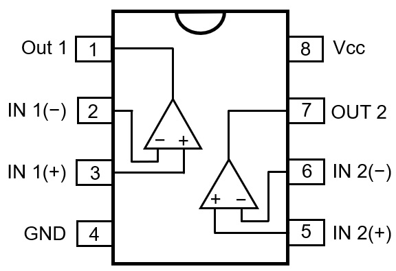
Figure 4. LM358 pin assignments
The voltage supplied to the (+) terminal of the comparator is obtained from the voltage that will cause a malfunction to the external device if the output voltage of the power supply rises further. The voltage applied to the (+) terminal is calculated by dividing the voltage between R1, R2, and R3, but set it just above the (-) reference voltage.
Specifications of the OVP
The output voltage of the DC power supply in normal operation is 13.8V. If it exceeds 16V for some reason, the OVP activates and cuts the circuit between the output of the DC power supply and the load with the mechanical relay. I built this unit as an external device without modifying the DC power supply.
Main parts used for the OVP
(1) D1
Determines the voltage to be applied to the (-) terminal, which is the reference voltage for the comparator. I used an 8V Zener diode for D1 from the parts I have in my parts box. Therefore, approximately 8V is applied to the (-) terminal.
(2) R1、R2、R3
Since the OVP must cut off the output voltage of the DC power supply if it becomes 16V, I calculated the voltage applied to the (+) terminal from the divided voltage of R1, R2, and R3 so that it became the reference voltage of 8V. R3 is a variable resistor, so the threshold voltage of pin 3 can be changed slightly.
When even Vcc becomes 16V, the voltage applied to pin 2 is the Zener voltage of 8V. It can be seen that the resistance value of the series connection of R2+R3 and the value of R1 are the same. Select the resistance value so that R1=R2+R3. If the variable resistor of R3 is adjusted under this condition, 8V is applied to pin 3 similar to that of pin 2.
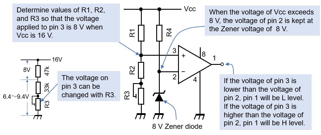
Figure 5. Comparison between the reference voltage and the set voltage
(3) D2
I used an 1N4002, which is a silicone diode, for rectifying because I have it a lot of them in my parts box. When the mechanical relay is turned ON or OFF, a counter electromotive force is generated at both ends of the coil, so a diode is connected in parallel with the coil as a countermeasure against this electromotive force surge.
(4) D3
When the relay is turned ON, the positive line (red) in Figure 3 is cut off by the relay. At this time, Q2 drives a red LED (D3) to indicate that the voltage has been cut off because of overvoltage.
(5) R3
I connected a 50kΩ variable resistor in series with R2 so that 8V is applied to pin 3 of IC1. The voltage applied to pin 3 can be changed from 6.4 to 9.4V by adjusting R3.
(6) R4
I selected a resistor that allows the 8V Zener diode to operate at a constant voltage. Here, it is set to 22kΩ.
(7) RL1
A mechanical relay that switches the DC line. I selected a relay according to the current capacity to be used. However, the electromagnet part of the relay must operate at DC 15-16V.
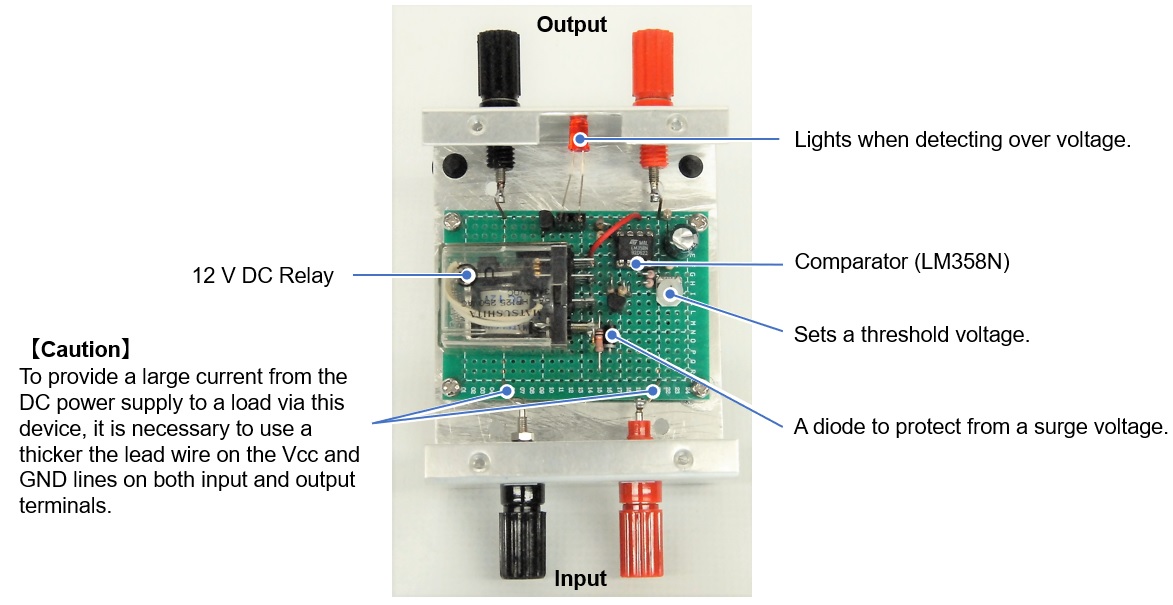
Assembling
I mounted the parts onto a universal board. As I had a DC 12V relay as shown in Figure 6, so I used it. The relay is selected according to the amount of current that flows. For the IC-705, the current flowing at 10W full power is about 3A. If you connect a 100W transceiver, a maximum of about 20A will flow, so it is of course necessary to select a relay that can withstand a large current. It is also necessary to use thick wire where there is a large current flow in wire that is used on the universal board.
Adjustment
Connect the DC power supply and a load to the OVP, as shown in Figure 7 below. Connect an appropriate load and voltmeter to the output terminal of the OVP. For this article, I used two 10Ω cement resistors connected in parallel as a load.
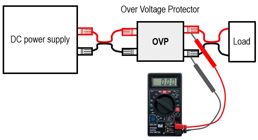
Figure 7. Connection diagram
Set the voltage of the DC power supply to 13.8V. Make sure that the output terminal of the OVP has a voltage of 13.8V. Gradually increase the DC power supply voltage and stop it at around 16V or your desired cutoff voltage. Adjust R3 variable resistor to where the output of the OVP is zero. Since the comparator has a hysteresis characteristic, repeat this adjust R3 several times so that the relay makes a clicking sound and turns ON at around 16V. When the relay is turned on, the red LED warning lamp lights up.
About the LM358 as a comparator
The LM358 was originally an operational amplifier (Op-Amp), but this time I used it as a comparator. A simple operating principle of the comparator is explained in this WEB magazine article titled "Technical Trivia by Dr. FB" Please read it when you have a chance.
I will continue to use the LM358 for overvoltage detection next time, but I will build a device with a P-channel MOSFET for the switching part of the power supply cutoff instead of the mechanical replay.
CL
Short Break backnumber
- How many colors do you see when a colored disc is rotated at high speed?
- Making a dual Positive/Negative voltage power supply in a single box, for experiments
- Building of an RF Volt-Ammeter for QRP operation
- White noise generator project
- One day electronics project – Making a simple antenna tuner for QRP operations
- Can the RHM12 portable antenna be matched with a bicycle body on HF?
- Making an “ON AIR” lamp using LM358
- Making a simple anemometer
- Making a sound machine say “Good morning. Thank you for everything.”
- Electronics project for the 10 MHz reference signal generator (2)
- Electronics project for the 10 MHz reference signal generator (1)
- Making a straight type AM radio using a TA7642 IC
- About splitters
- Electronics project for FB NEWS: Making a decoration light string
- Making a Simple Electric Field Strength Meter
- Building a simple QRP power meter
- Building a 20 Amp electronic DC load device using an N-channel MOSFET for the load
- Building an automatic backup power switching unit
- Overvoltage protection device using LM358: Part 2
- Building an Over Voltage Protector: Part 1
- Making a 50 MHz monoband MLA without a variable capacitor
- Making a 50 MHz monoband MLA.
- Let's connect a computer headset to the IC-705
- Building a microphone selector
- Building an audio amplifier using an LM386 IC chip
- An External Keypad for Icom Transceivers
- After all, is the receiver good for Up-conversion?
- Find the gain of the stack antenna
- The mystery of controlling the microphone and PTT with only two wires
- RFID tag