


Short Break
Overvoltage protection device using LM358: Part 2
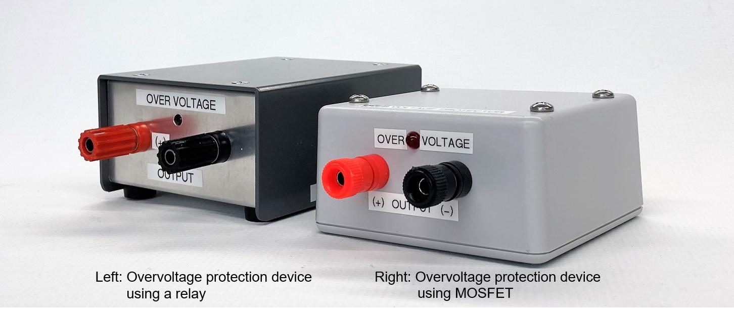
Using a P-channel MOSFET transistor for switching
Outline of the MOSFET overvoltage protection circuit
In Part 1 of the previous article, I made a device that uses a mechanical relay to shut off the power supply line to protect the equipment connected to it from overvoltage when the voltage of the DC power supply increases above a set voltage. This time, in Part 2, the circuit that cuts off the power supply line will be changed from a mechanical relay to a MOSFET transistor to make it completely solid state.
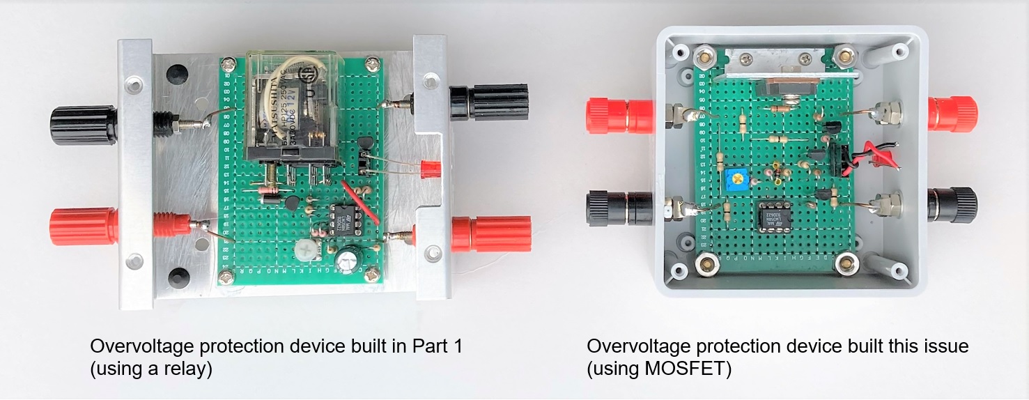
Figure 1. Inside view
MOSFETs are very convenient semiconductors for switching, if you understand the principle. In this issue of FB NEWS, Dr. FB's article on Trivia briefly explains the operating principle of the MOSFET transistor used here. I think that you can deepen your understanding if you read Part 1 and this article together.
Figure 2 shows the configuration diagram of the overvoltage protection device that I built this time. As with the mechanical relay prevention device in Part 1, I will not modify the DC power supply used this time.
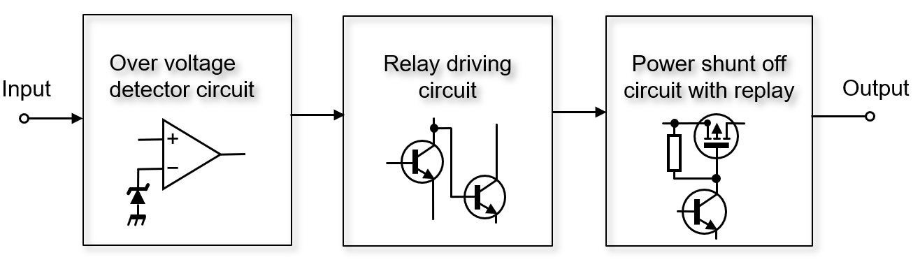
Figure 2. Configuration diagram of overvoltage protection circuit using MOSFET
The DC power supply to the radio is often rated at 13.8 V DC ± 15%. If the applied voltage is low, the radio may not work properly, but it is unlikely to be damaged. However, if the applied voltage is high, the risk of damage increases, so be careful. In other woRDS, 13.8 V plus 15% is 15.87 V or higher, and is strictly prohibited.
This overvoltage protection device protects the electronic devices from overvoltage when the output of the DC power supply exceeds the specified value for some reason. The device detects overvoltage with a comparator. Normally, a voltage that is approximately the same as the output voltage of a DC power supply is supplied to the load through an overvoltage protection device. When the voltage of the DC power supply becomes around 13.8 V plus 15%, the MOSFET turns OFF and the power supply circuit is cut off.
Two key parts used for production
Figure 3 is a circuit diagram of an overvoltage protection device that uses a comparator and a P-channel MOSFET. There are not that many parts used, and there are no special parts. The electronic operation is relatively easy.
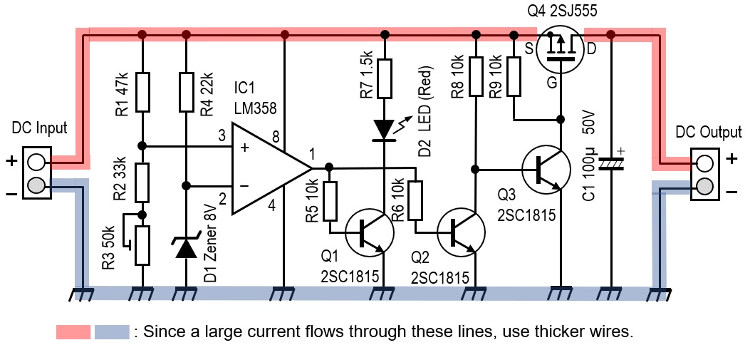
Figure 3. Schematic of the overvoltage protection device
There are two key parts. One is the triangular symbol drawn in the center of the schematic diagram. This is an LM358 operational amplifier that is used as a comparator. The other is the P-channel MOSFET used for Q4. I had a 2SJ555 P-channel MOSFET manufactured by Renesas on hand, so I used it. According to the data sheet, the resistance (RDS) in the ON state is very low at 0.017 Ω, and the drain current (ID) can be as large as 60A. I used this 2SJ555, but I think that any FET will work as long as it is a P-channel MOSFET. Please choose the one that suits you.
Circuit operation description
Figure 4 is an internal block diagram of the LM358. Two operational amplifiers (Op-Amps) are included in one package. An Op-Amp operates as an original amplifier when negative feedback is applied to the circuit. When operating as a comparator, no negative feedback is applied.
The comparator compares the potential difference between the two input terminals (+) and (-). It sets the output terminal to HIGH or LOW, depending on the state of the potential difference. This time, I will use this function to compare the reference voltage and the output voltage of the DC power supply with a comparator. If the output voltage of the DC power supply is higher than the reference voltage, the output of the comparator becomes HIGH, and the signal drives the subsequent transistor, turns OFF the MOSFET, and shuts off the output of the DC power supply.
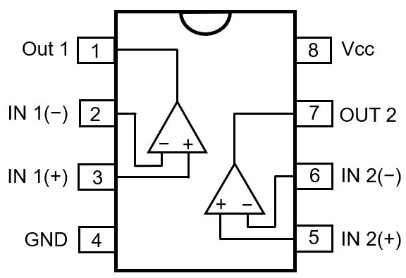
Figure 4. Pin layout of LM358
The voltage supplied to the (+) terminal of the comparator is calculated by dividing the voltage between R1 and R2, but it is set just above the reference voltage (-).
Specifications of overvoltage protection device
The output voltage of the DC power supply is 13.8 V DC. If it exceeds 15.87 V (15% above 13.8 V DC) or the set voltage for some reason, this overvoltage protection device activates. and the output of the DC power supplied will be cut off by this device. For this device, the DC power supply you are using will not be modified and will be an external device. Also, although the ID of the MOSFET used in the circuit is very large, this device should have internal wiring that can safely pass the current between the DC power supply and the radio.
Main parts used for the overvoltage protection device
(1) D1
Determines the voltage to be applied to the (-) terminal, which is the reference for the comparator. I used an 8 V Zener diode for D1 from the parts in my parts box. Therefore, about 8 V is applied to the (-) terminal of the comparator.
(2) R1, R2 and R3
When the output voltage of the DC power supply becomes 15.87 V, the DC power supply and the load are cut off by this overvoltage protection device, so the voltage applied to the (+) terminal is referenced from the divided voltage of R1 and R2 + R3. Calculate the resistor values so that the voltage is 8 V. R3 is a variable resistor so that the threshold voltage of pin 3 can be changed slightly.
When the DC power supply is turned ON, 8 V of Zener voltage is applied to pin 2. It can be seen that the resistance value of the series connection of R2 + R3 and the value of R1 are the same. Select the resistance value so that R1 = R2 + R3. By using R3 as a variable resistor, 8 V can be applied to pin 3.
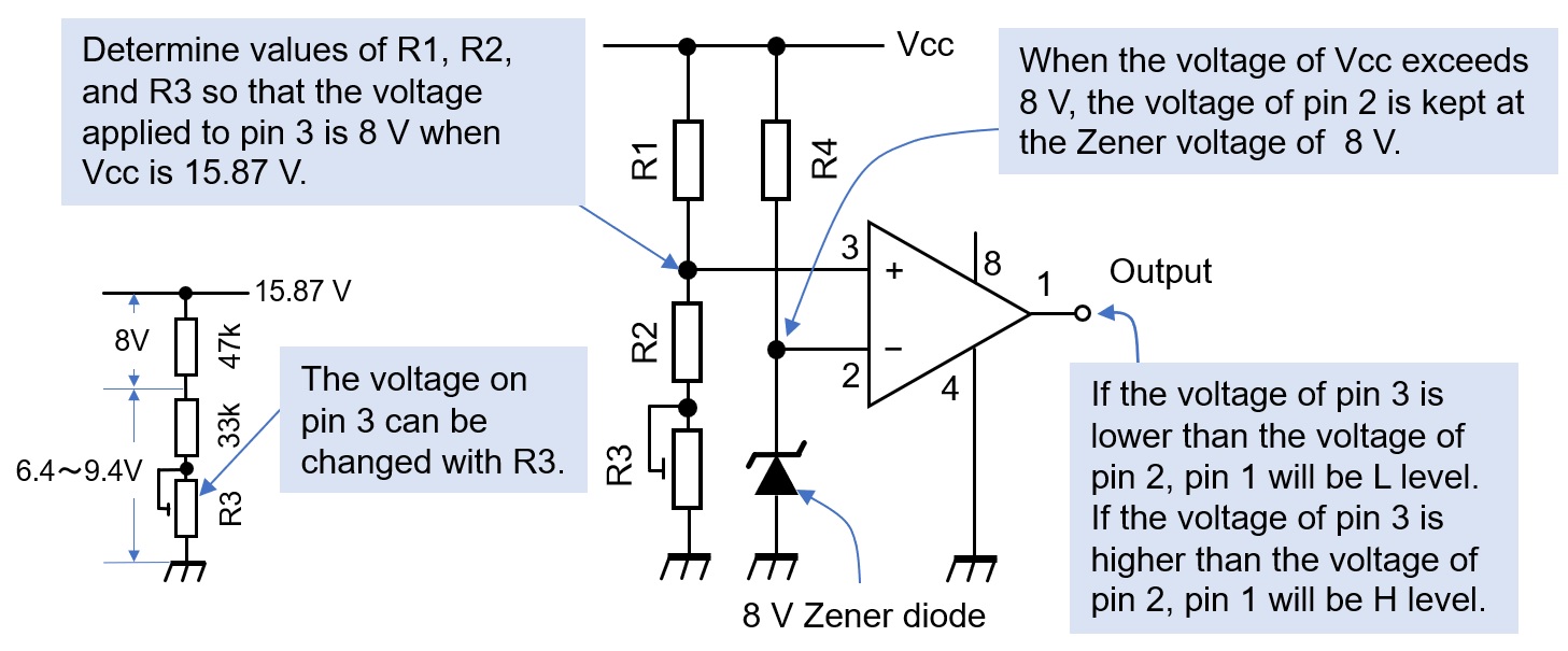
Figure 5. Comparator reference and comparison voltage settings
(3) Q1, Q2, and Q3
I used general-purpose 2SC1815s. Since they are only used to turn the MOSFET ON or OFF, there is no problem using any NPN transistor for small signals.
(4) Q4
It is a P-channel MOSFET. When the voltage applied to the gate is lower than the source voltage, the source and drain are turned ON and both electrodes are conductive. On the contrary, when the gate voltage becomes equal to or higher than the source voltage, the source and drain is turned OFF and both electrodes are not conductive.
(5) D2
This is an LED that lights up by Q1, which turns ON when pin 1 of IC1 becomes HIGH when the input voltage becomes higher than the reference voltage.
(6) R3
Connect a 50 kΩ variable resistor in series with R2 so that 8 V is applied to pin 3 of IC1. The voltage applied to pin 3 can be adjusted by R3 to between 6.4 and 9.4 V.
(7) R4
Select a resistor that allows the 8 V Zener diode to operate as a voltage regulator. Here, the resistor is 22 kΩ.
Building
Mount the parts onto the universal board. The MOSFET was attached to a small heat sink, as shown in Figure 6. But in the experiment, the current was about 5 A at 13.8V, the on-resistance (RDS) of the MOSFET was as low as 0.017Ω, so almost no heat was generated. If you connect a 100 W radio, the maximum flow is about 20 A. In this case, it is 6.8 W from P = I2・R in the calculation, but it was actually a little warmer. Even so, a large current of 20 A flows through a part of the internal wiring, so it is necessary to consider using thick wire for the wiring.
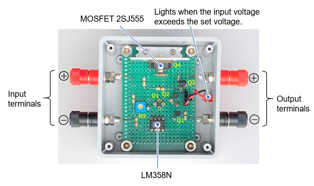
Figure 6. Inside view of the overvoltage protection device
Adjustment and operation check
Connect the output terminal of the DC power supply and the input terminal of the overvoltage protection device as shown in Figure 7. Connect an appropriate load, such as a radio and voltmeter, to the output terminal of the overvoltage protection device.
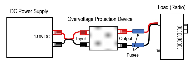
Figure 7. Connections of the overvoltage protection device
Set the output voltage of the DC power supply to 13.8 V. At that time, check that the output terminal of the overvoltage protection device is 13.8 V. Gradually increase the voltage of the DC power supply and stop it at around 15.87 V (13.8 V + 15%). Adjust the R3 variable resistor in the schematic diagram in Figure 3 to where the output of the overvoltage protection device is zero.
Since the comparator has a hysteresis characteristic, repeat this adjustment several times to adjust R3 so that the output voltage becomes zero at around 15.87 V. When the overvoltage protection device detects overvoltage, the red LED lights up.
About LM358
The LM358 is an Op-Amp IC chip, but this time I used it as a comparator. Please read the simple operating principle of the comparator that is explained in this FB magazine "FB Trivia."
Precautions regarding production and use
This unit is inserted between an IC-705 and the DC power supply, and when the output voltage of the DC power supply exceeds 13.8 V by 15 % or more, the power supply circuit between the power supply and the IC-705 is cut off. After building, I have conducted experiments to adjust the resistance value of the load and let it flow up to about 10 A, and confirmed that it operates normally. If you want to use it with a higher rating, making and using it is your responsibility.
CL
Short Break backnumber
- How many colors do you see when a colored disc is rotated at high speed?
- Making a dual Positive/Negative voltage power supply in a single box, for experiments
- Building of an RF Volt-Ammeter for QRP operation
- White noise generator project
- One day electronics project – Making a simple antenna tuner for QRP operations
- Can the RHM12 portable antenna be matched with a bicycle body on HF?
- Making an “ON AIR” lamp using LM358
- Making a simple anemometer
- Making a sound machine say “Good morning. Thank you for everything.”
- Electronics project for the 10 MHz reference signal generator (2)
- Electronics project for the 10 MHz reference signal generator (1)
- Making a straight type AM radio using a TA7642 IC
- About splitters
- Electronics project for FB NEWS: Making a decoration light string
- Making a Simple Electric Field Strength Meter
- Building a simple QRP power meter
- Building a 20 Amp electronic DC load device using an N-channel MOSFET for the load
- Building an automatic backup power switching unit
- Overvoltage protection device using LM358: Part 2
- Building an Over Voltage Protector: Part 1
- Making a 50 MHz monoband MLA without a variable capacitor
- Making a 50 MHz monoband MLA.
- Let's connect a computer headset to the IC-705
- Building a microphone selector
- Building an audio amplifier using an LM386 IC chip
- An External Keypad for Icom Transceivers
- After all, is the receiver good for Up-conversion?
- Find the gain of the stack antenna
- The mystery of controlling the microphone and PTT with only two wires
- RFID tag