


Short Break
Making a 50 MHz monoband MLA.
The first impression of the MLA
It's been a year since Icom released the IC-705 Portable transceiver. I had an opportunity to use a magnetic loop antenna that covers 7 to 28 MHz. This antenna is called a Magnetic Loop Antenna (hereafter called MLA).
I connected the MLA to my IC-705 in my office on the 5th floor and tried to receive on the 7 MHz band. It was amazing and I was surprised that the signal came in to the radio from the outside through a window glass. The antenna is like an active antenna. The ham friends who were with me even praised it as "amazing."
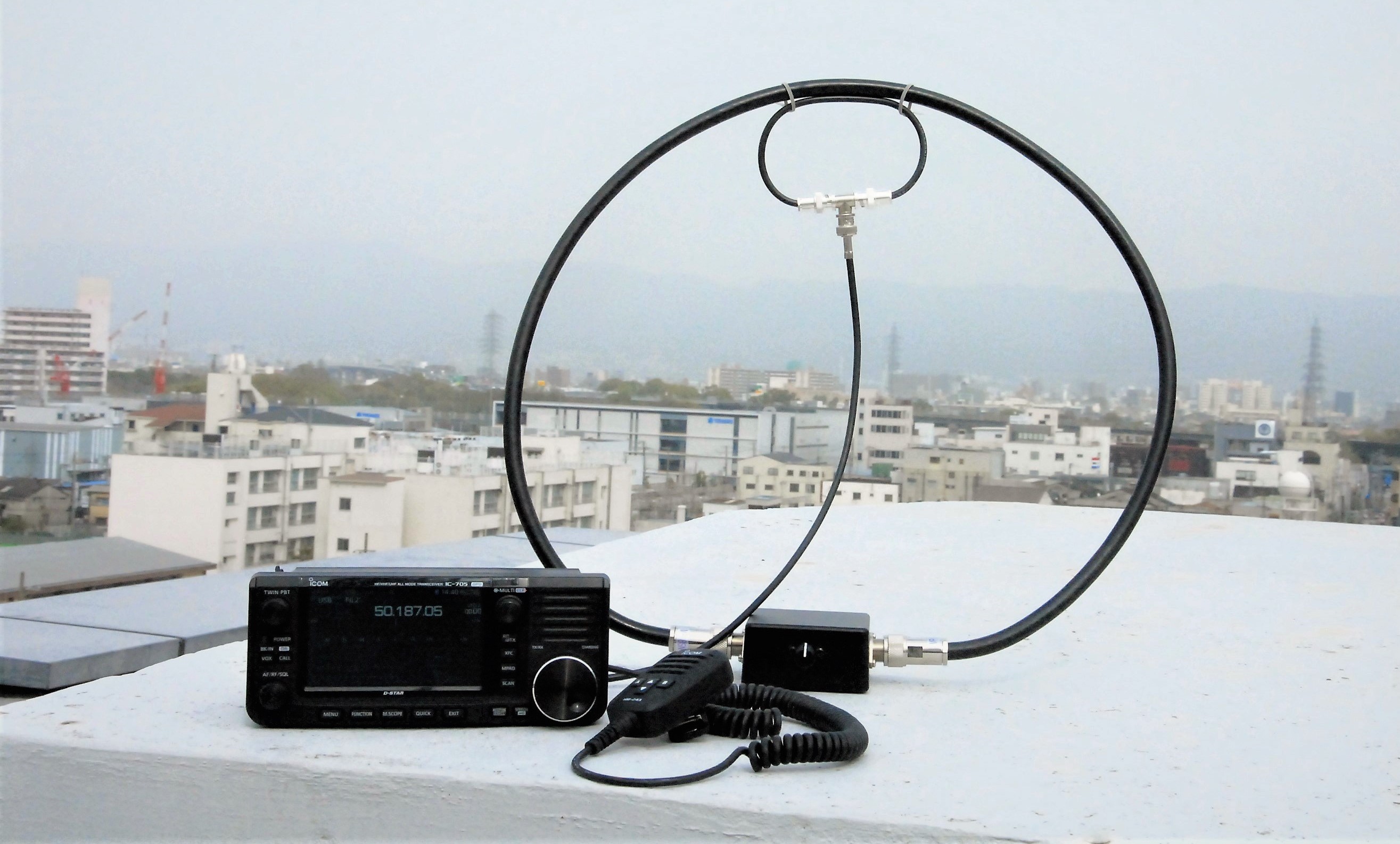
Figure 1. The 50 MHz monoband MLA
One day, I hiked to the top of a mountain near my home in southern part of Osaka. I decided to try an experiment on 7MHz, which I usually use on CW. and connected the MLA to the IC-705. The reception was as good as it was in the office. However, transmission was not as impressive as reception. The radio output was 5W (QRP), but even if I called a station with a strong signal, I couldn't get a call back from the station, and I was honestly frustrated. When I made CQs on SSB or CW, there was a reasonable response.
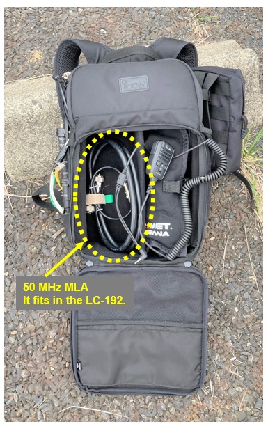
Figure 2. It fits in the LC-192.
However, I did not experience a pile-up. I was expecting to receive a little pile-up because I transmitted from a location 1000 meters above sea level, but I was disappointed. Even so, the MLA is compact enough to be carried in a backpack, and I thought it would be a perfect antenna for people who enjoy hiking and operating amateur radio outdoors. Then, I decided to make monoband MLA specifically for the 50 MHz band, which I often use when I go outdoors. In this article I will explain the making of this antenna.

Operating principle of an MLA
If you search for MLA on the Internet, you will find many articles and sites that describe the operating principle. As the author I should write about the principle and theory of operation more in detail of antennas, but I am not good at the theory and principle of the MLA. Therefore, I explain the principle a little in this article and I will concentrate on explaining how to make it.
Figure 3 shows the MLA equivalent circuit. The circuit consists of two coils, one on the primary side and the other on the secondary side, like a transformer. Actually, no coil is found in the antenna element, but it is composed of two loops that act as inductance (coil) at high radio frequencies (hereafter called RF). The smaller loop is called the feeding loop on the primary side. The feeding loop inputs the RF energy from the main loop to the radio during receive, and outputs the RF energy from the radio during transmit through the main loop.
The larger loop is on the secondary side. It is called the main loop, and the RF energy generated on the primary side is induced to the secondary side by electromagnetic induction, and the RF energy is radiated from the main loop into the air.
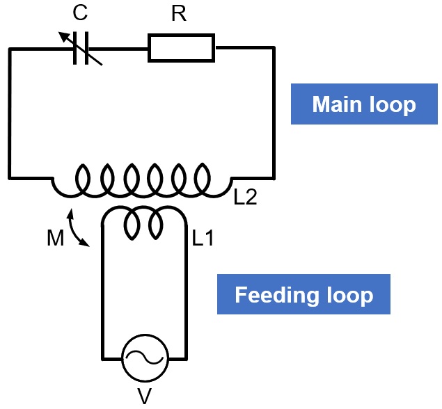
Figure 3. Equivalent circuit of MLA
For the two loops (elements), both the feeding loop and the main loop are made with a thick coaxial cable, as shown in Figure 4, and connectors are attached to both ends. Both loops form an RLC resonant circuit. In order to efficiently radiate the signals, the main loop must be a resonant circuit that matches the frequency set on the radio. The principle is that a large current flow through the loop due to resonance, and a magnetic field is generated around the loop. For reference, the resonance frequency of the main loop can be calculated by the following equation. This is the formula I have seen many times in electronic books for radio operators.

When the main loop is resonated, the impedance becomes very low, so impedance conversion is performed in the feeding loop and the impedance is raised to 50 Ω. The main loop and the feeding loop are connected by electromagnetic induction like a transformer.
Dimensions of MLA
The MLA to be made is exclusively for the 50 MHz band. It is important that the antennas made for amateur radio operators like me, who are half hiking and half radio operating, fit in a backpack.
A coaxial cable is used for the loop of the element to reduce the size. Using copper or aluminum pipes can be expected to increase the surface area and bandwidth of the antenna, but considering portability, I decided to not use metal pipes. The coaxial cable that makes the main loop is 8DFB, which is a 50 Ω coaxial cable that is easy to get in Japan. I think RG-8 is very similar to 8DFB. Any coaxial cable can be used for the loop, but I think the thicker the cable may have better performance. Since both the center conductor and the outer conductor of the coaxial cable are used as the antenna element, both conductors are short-circuited in the matching box. This will increase the matching bandwidth.
I used RG-58 coaxial cable for the element of the feeding loop. It is not necessary to make a difference in the thickness of the coaxial cable between the main loop and the feeding loop, but I chose RG-58 because I wanted to make a smaller loop, and wanted to use the T-type BNC connectors for miniaturization.
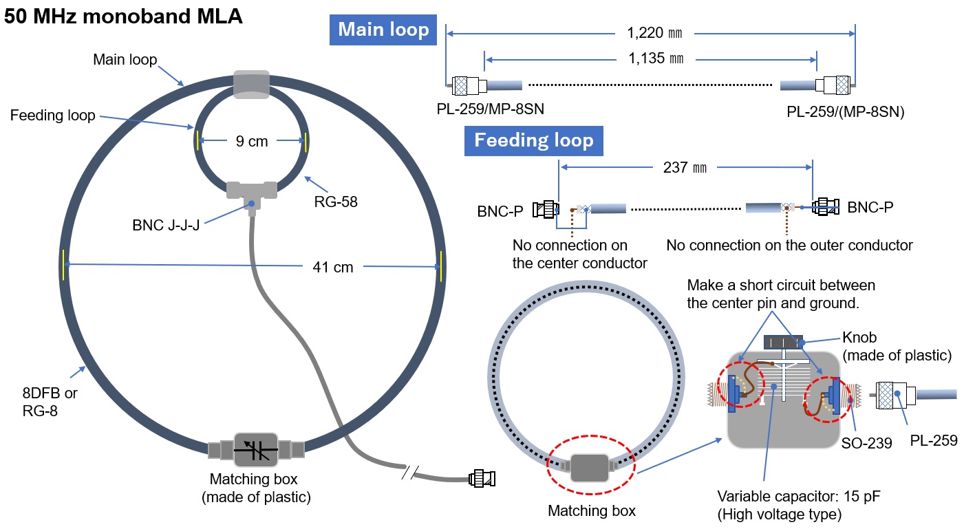
Figure 4. 50 MHz monoband MLA dimensions
Making the main loop
I made the main loop with thicker coaxial cable, as shown in Figure 4 above. The length of the coaxial cable is roughly determined based on the information obtained from books. After that, I adjusted the length of the coaxial cable by cut and try using a dip meter, and fix the resonance frequency at 50.200 MHz. Details will be explained later in adjusting the main loop.
The point here is how to adjust the length of the main loop by cut and try. If the PL-259 UHF connectors attached to both ends are the ordinary coaxial male connectors shown on the left side of Figure 5, once soldered to the coaxial cable, it is almost impossible to remove and reattach. You cannot adjust the length with this connector. Therefore, with the connector shown on the right side of Figure 5, the length of the coaxial cable can be adjusted relatively easily by cutting and trying because the part to be soldered is only the core wire part like a Type-N connector.

Figure 5. Two different connectors for coaxial cables
The main loop uses both the center and outer conductors of the coaxial cable as radiating elements. Therefore, the center and outer conductors are shorted together, as shown on the left in Figure 6. Since it is difficult to make a short-circuit in the connector, it is done in the matching box, as shown in Figure 8.

Figure 6. Wiring diagram of the main loop and feeding loop
Making the feeding loop
Connect the feeding part of the feeding loop as shown in the right side of Figure 6 above. In this illustration, each end of the loop does not have a connector drawn, but in reality, it is made using a BNC male connector as shown in Figure 7 below so that it can be removed. The element of the feeding loop is made of RG-58. The BNC connectors that attach to both ends of the coaxial cable require some work. When installing the BNC connector, the BNC on one side does not connect the center conductor, and the BNC connector on the other end does not connect the outer conductor. For details, refer to the wiring diagram on the right side of Figure 6. The length of this coaxial cable is about 237 mm, as shown in the design drawing in Figure 4. The adjustment is described in the section on adjusting the feeding loop below.
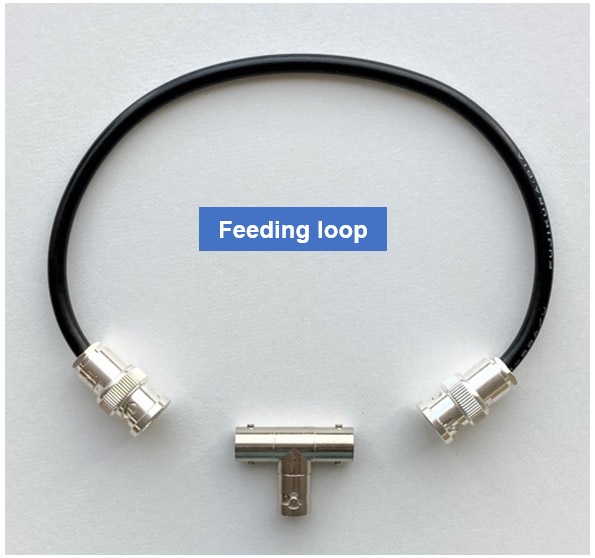
Figure 7. Completed the feeding loop
Making the matching box
Install a variable capacitor shown in the equivalent circuit in Figure 3 into the matching box. The main loop has two PL-259 UHF connectors on both ends of the loop so that it can be removed from the matching box for greater portability. See Figure 8 for the matching box structure.
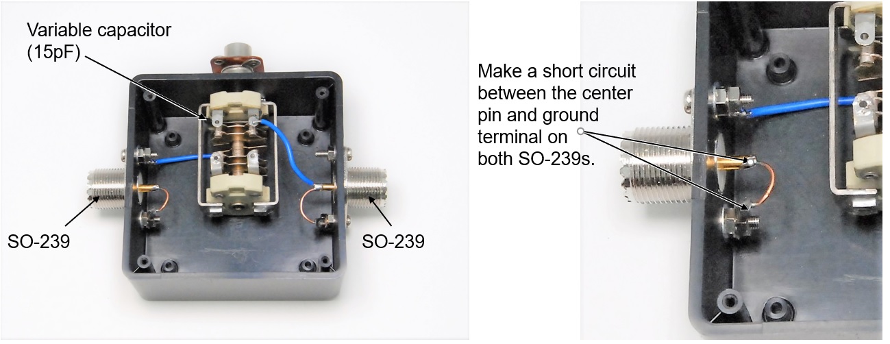
Figure 8. Inside the matching box
I got the variable capacitor at a flea market before, and it is a used capacitor. The variable capacitor shown in Figure 8 has two 15 pF capacitance elements connected in parallel. At first, I used it as 30 pF capacitor, but since it was very critical to tune to the desired frequency with the variable capacitor rotation, I disconnected the one 15 pF capacitor element from the original capacitor, and I use only one.
Recently, it is difficult to obtain variable capacitors, even used ones. I have heard that there are many cases where components are difficult to obtain and making an antenna or unit is abandoned, even if construction articles are posted. This time, I made an MLA using a variable capacitor, but I would like to write an article to make a similar MLA using relatively easily available components other than the variable capacitor, at another time.
The main loop adjustment
Attach the main loop to the matching box without attaching the feeding loop. Place the coil of the dip meter inside the main loop, as shown in Figure 9. The loop with a diameter of 40 cm works as an RLC resonance circuit. First, find the resonance point using the dip meter as shown, and slowly rotating the variable capacitor knob.
You can find the dip point (resonance point) by carefully turning the adjustment knob of the dip meter.
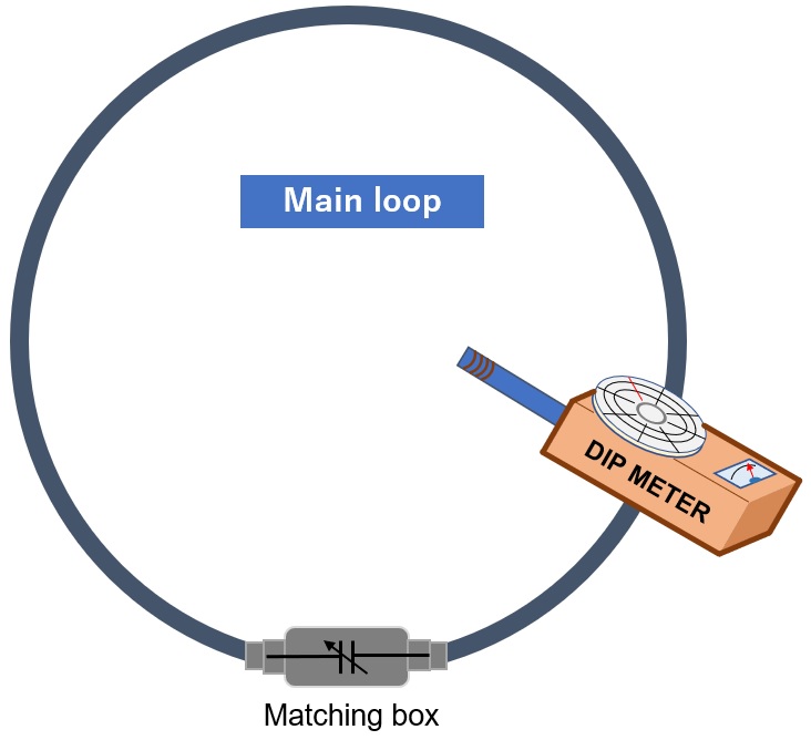
Figure 9. Measure the resonance frequency of the main loop with a dip meter.
If there is a resonance point at a frequency far below 50 MHz, I think that the resonance point cannot be found by adjusting the variable capacitor. In this case, it's a hassle, but you need to shorten the coaxial cable a little. The special type of PL-259 connector shown on the right side of Figure 5 is useful here.
If the adjustment of the variable capacitor is very critical, the capacitance of the variable capacitor is too large. In that case, I think that it can be reduced by physically removing some rotors and stators of the variable capacitor and thereby lowering the capacitance.
The feeding loop adjustment
Attach the feeding loop to the main loop as shown in Figure 10 below and attach completed MLA to the matching box. The main loop and the feeding loop are connected by the principle of electromagnetic induction. Connect an antenna analyzer or network analyzer to the end of the completed MLA through a coaxial cable.
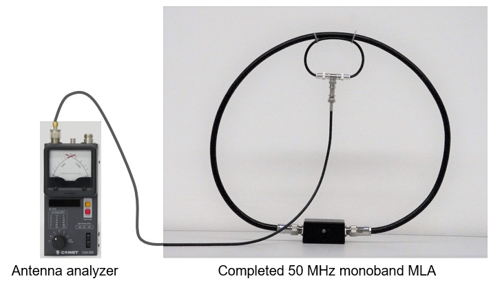
Figure 10. Feeding loop adjustment
Adjust the length of the feeding loop to minimize the SWR value on the antenna analyzer. To adjust this loop length, remove the BNC connector from the RG-58 and adjust the length of the coaxial cable. In the MLA I made shown in Figure 10, I was able to adjust the SWR to 1.1:1 at 50.200 MHz. The main loop and the feeding loop are held together with tie wraps.
Set the IC-705 to receive on 50 MHz. Turning the variable capacitor on the MLA changes the noise sound level heard from the IC-705 speaker. The maximum noise level is where MLA is approximately matched. Set the IC-705 in the RTTY mode for pinpoint matching and to adjust during transmit. Adjust so that the SWR value can be observed on the display of IC-705. If you turn the variable capacitor slowly while transmitting, there should be a point where the SWR will drop.
Summary
As soon as I took the adjusted MLA outdoors, the SWR became 3:1 or more. In order to adjust the SWR, I turn the variable capacitor knob while transmitting with the IC-705 to minimize the SWR value, but even where the SWR was the lowest, if I let go of the tuning knob of the variable capacitor, the SWR deteriorated. I felt that the antenna was greatly affected by the operating frequency, the environment where the antenna is used, and the distance between the human body and the antenna.
I'm not sure if the MLA I made is a good performing antenna because I have not done enough comparative tests yet. So, I have two homework assignments. One is to do comparison testing with other antennas. The other one is to make a similar MLA with a substitute for the hard-to-find variable capacitor.
CL
References / Materials
Denpasha HAMworld November 2019 issue, January 2020 issue, March 2020 issue, May 2020 issue "From the encounter with the electromagnetic field antenna to today"
CQ Publishing Co., Ltd. CQ ham radio Separate Volume QEX No. 25 “Introductory Making and Learning MLA”
Short Break backnumber
- How many colors do you see when a colored disc is rotated at high speed?
- Making a dual Positive/Negative voltage power supply in a single box, for experiments
- Building of an RF Volt-Ammeter for QRP operation
- White noise generator project
- One day electronics project – Making a simple antenna tuner for QRP operations
- Can the RHM12 portable antenna be matched with a bicycle body on HF?
- Making an “ON AIR” lamp using LM358
- Making a simple anemometer
- Making a sound machine say “Good morning. Thank you for everything.”
- Electronics project for the 10 MHz reference signal generator (2)
- Electronics project for the 10 MHz reference signal generator (1)
- Making a straight type AM radio using a TA7642 IC
- About splitters
- Electronics project for FB NEWS: Making a decoration light string
- Making a Simple Electric Field Strength Meter
- Building a simple QRP power meter
- Building a 20 Amp electronic DC load device using an N-channel MOSFET for the load
- Building an automatic backup power switching unit
- Overvoltage protection device using LM358: Part 2
- Building an Over Voltage Protector: Part 1
- Making a 50 MHz monoband MLA without a variable capacitor
- Making a 50 MHz monoband MLA.
- Let's connect a computer headset to the IC-705
- Building a microphone selector
- Building an audio amplifier using an LM386 IC chip
- An External Keypad for Icom Transceivers
- After all, is the receiver good for Up-conversion?
- Find the gain of the stack antenna
- The mystery of controlling the microphone and PTT with only two wires
- RFID tag