


Short Break
About splitters
This article was originally published as No. 69 Splitter issued in February 2019 in a corner "Have a fun for Electronics projects," and has been translated into English with the permission of the writer. (https://www.fbnews.jp/201902/electronics/index.html)
Writer: Kiyoshi Sakurai, JA3FMP
Translation: FB NEWS Editorial section
There are times when you want to use multiple receivers with a single antenna. In this case, you will need a splitter.

Figure 1. An example of 2-Way splitter connections
If an original signal from the antenna is divided into two as shown the diagram Figure 1, the power will be halved, so even if there is no loss at all in the circuit, the output of each will be -3 dB. The following circuit using a high frequency transformer is well known as a splitter.
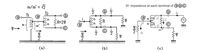
Figure 1. 2-Way splitter
Looking at Figure 1 in the case of a 2-Way splitter, the impedance at the midpoint of the splitter with transformer T2 is W/2, which is 25 ╬® for a 50 ╬® impedance. To match this, T1 is 50 ╬®/25 ╬®, and the winding ratio is ŌłÜ2:1. The R on the output side works to balance the two outputs when they are out of balance, and in the case of 3-Way splitter, the transformer and balancing resistors are configured as shown in Figure 2 to distribute from one input to each of the three outputs.

Figure 2. 3-Way splitter
Based on these conditions, I experimented with 2-Way splitter. Two transformers are required for the splitter, and four transformers are required for 3-Way splitter. The size of the ferrite core used in the transformer is 14 mm x 23 mm, with two holes like a pair of glasses.
T2 to T4 are transformers that is a 1:1 midpoint tap type, but T1 needs to be ŌłÜ2:1 for a 2-Way splitter and ŌłÜ3:1 for a 3-Way splitter. However, since the number of turns is small, it is not easy to change the ratio. I will try to keep the ratios as close as possible, so for the 2-Way splitter, I made transformers shown in Figure 3 below.
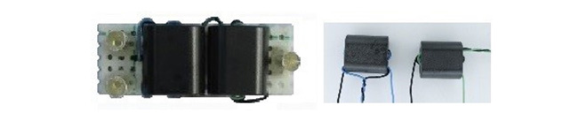
Figure 3. 2-Way splitter and its transformers
The frequency response for the 2-Way splitter I made is as follows.
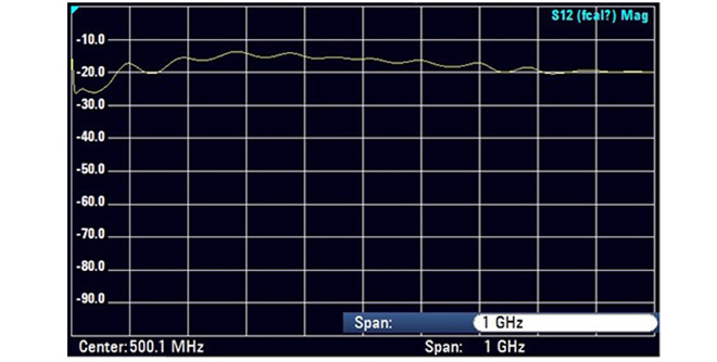
Figure 4. Frequency response for the 2-Way splitter
As you can see, the characteristics are far from the target and it is not what I expected. Above all, I was disappointed because there was no good part within 10 dB. The core is designed for RF use, and I thought that if I wound the wires appropriately, I would get a reasonable characteristic. I am sure there are many reasons for this, but even after reviewing the wire routing and grounding, there was no significant improvement in the characteristics. The low frequency drop may be due to the winding method of the transformer or the material of the core, and the wide frequency drop may be due to the winding.
I took out only T2 and used a tracking generator to get the characteristics of the transformer itself. There should be almost no loss, but there was more than a few dB of loss, and it did not improve even after changing various things such as the way the wires were wound. I found out that it cannot be improved without reviewing the basic parts such as the core material and the windings, so I would like to start all over again.
Since I failed with the transformer type splitter, I will experiment with the resistor type next. The resistor type splitter will have the following circuit.
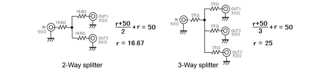
Figure 5. Splitter circuits using resistors instead of transformers
In this case, the output is -6 dB for a 2-Way splitter and -8.5 dB for a 3-Way splitter compared to the input, which means that the scale of the signal strength S-meter on a radio for reception drops by 1 for a 2-Way splitter and by 1.5 for a 3-Way splitter. For more information about the S-meter, refer to the table at the end of this article.
The frequency response of this circuit using chip resistors is not so bad, and it seems to have better characteristics than ferrite core transformers, especially in the low frequency range. In the case of a 2-Way splitter, this method may be easier and better if the S-meter scale is not so much affected by the reception, even if it goes down by one scale. The frequency response of the 2-Way splitter with resistors is as follows.
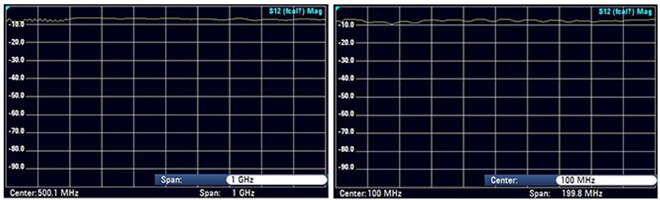
Figure 6. Frequency response for 2-way splitter with resistors
The left figure in Figure 6 shows the characteristics from 1 MHz to 1 GHz, and the right figure shows an enlarged version of the characteristics below 200 MHz, which seems to be slightly distorted. I don't know the cause of the disturbance, but it doesn't seem to have much effect. Figure 7 shown below shows the SWR characteristics of the 2-Way splitter.

Figure 7. SWR characteristic of the 2-Way splitter
The SWR was good, less than 1.1:1. The SWR was only measured up to 230 MHz because it was measured with an MFJ-226 antenna analyzer, but it does not seem to be that bad at higher frequencies.
I put the 2-Way splitter made with a universal board into a plastic case. The finished unit looks like this.

Figure 8. Completed resistor type 2-Way splitter
There is no significant difference in the characteristics of a 3-Way splitter unit using resistors, except for a slight increase in loss from -6dB to -8.5dB. Even in a resistor type distribution unit, if chip resistors are used, the frequency response is good due in part to the low resistance value. With the transformer type, I felt that it would be quite difficult to achieve a flat broadband frequency response within ┬▒3dB.
Signal strength on S-meter of a receiver
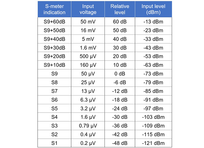
Figure 9. S-meter scale vs. input signal level
Short BreakŃĆĆbacknumber
- How many colors do you see when a colored disc is rotated at high speed?
- Making a dual Positive/Negative voltage power supply in a single box, for experiments
- Building of an RF Volt-Ammeter for QRP operation
- White noise generator project
- One day electronics project ŌĆō Making a simple antenna tuner for QRP operations
- Can the RHM12 portable antenna be matched with a bicycle body on HF?
- Making an ŌĆ£ON AIRŌĆØ lamp using LM358
- Making a simple anemometer
- Making a sound machine say ŌĆ£Good morning. Thank you for everything.ŌĆØ
- Electronics project for the 10 MHz reference signal generator (2)
- Electronics project for the 10 MHz reference signal generator (1)
- Making a straight type AM radio using a TA7642 IC
- About splitters
- Electronics project for FB NEWS: Making a decoration light string
- Making a Simple Electric Field Strength Meter
- Building a simple QRP power meter
- Building a 20 Amp electronic DC load device using an N-channel MOSFET for the load
- Building an automatic backup power switching unit
- Overvoltage protection device using LM358: Part 2
- Building an Over Voltage Protector: Part 1
- Making a 50 MHz monoband MLA without a variable capacitor
- Making a 50 MHz monoband MLA.
- Let's connect a computer headset to the IC-705
- Building a microphone selector
- Building an audio amplifier using an LM386 IC chip
- An External Keypad for Icom Transceivers
- After all, is the receiver good for Up-conversion?
- Find the gain of the stack antenna
- The mystery of controlling the microphone and PTT with only two wires
- RFID tag