


Short Break
Electronics project for the 10 MHz reference signal generator
Part 2: Building of the generator
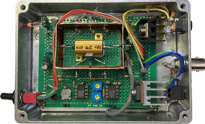
Inside view of the 10 MHz Reference Signal Generator
<Continued from March issue>
Review of the last issue
There is a convenient crystal oscillator that generates a 10 MHz signal by simply connecting 5 V and ground. This small unit is also called a clock module. In a component category, it is classified as a SPXO (Simple Packaged Crystal Oscillator). In part 2 of this article, I will refer to it as a crystal oscillator. The crystal oscillator consists of a crystal resonator and its oscillation circuit built into a small CAN. Note the size in Figure 1 below. This is an attempt to produce a 10 MHz reference signal generator using this module.
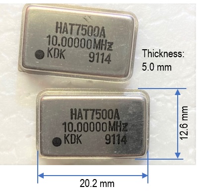
Figure 1. The crystal oscillator used in this test
Originally, this crystal oscillator was used to generate clock signals for logic circuits. Therefore, the outputs are logic high (H) and low (L). The output is then extracted as an RF signal through a capacitor.
Points examined since the previous experiment
While experimenting with the circuit shown in the previous issue, I found various problems and reexamined it. The final circuit, including minor modifications, is shown in Figure 2.
(1) Addition of power switch SW1
(2) Addition of LED D1 (blue) that lights up when the power switch is turned ON
(3) LED D2 (red) is added to indicate that the heater installed in the OCXO has turned ON
(4) Changed heater the mounting position from the source side to the drain side of Q1
(5) Addition of an output waveform shaping circuit
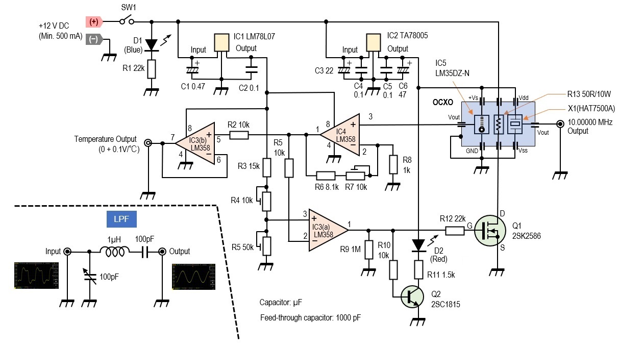
Figure 2. Whole circuit diagram
Although not an electrical circuit, the temperature inside the OCXO rises to nearly 40 ┬░C during operation of this circuit. For this reason, the PCB (Print Circuit Board) used inside the OCXO was changed from a paper copper PCB to a glass epoxy PCB (Figure 3).
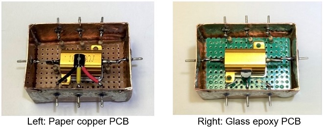
Figure 3. A different PCB is used in the final OXCO
Building
Please refer to the previous issue for the building of the OCXO. The building and assembly are basically the same as described in the previous issue, but the position of the LM35 temperature sensor is slightly different, as shown in Figure 3. Instead of placing the LM35 in contact with the surface of the heater, it is placed in contact with the surface of the crystal oscillator.
The OCXO and other components are mounted on a single-sided 70 x 100 mm glass epoxy PCB, with the OCXO unit taking up most of the board space, leaving little room for other components. I took time in laying out the components to make it look cool.
The OCXO unit is placed on the main board. The main board is connected to the input/output connectors and jacks mounted on the aluminum case so that they can be removed from the case using connector housings and header pins.
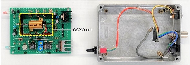
Figure 4. Inside view with the circuit board removed from the case
The case used was a die-cast aluminum box. The layout of the case is shown in Figure 5.
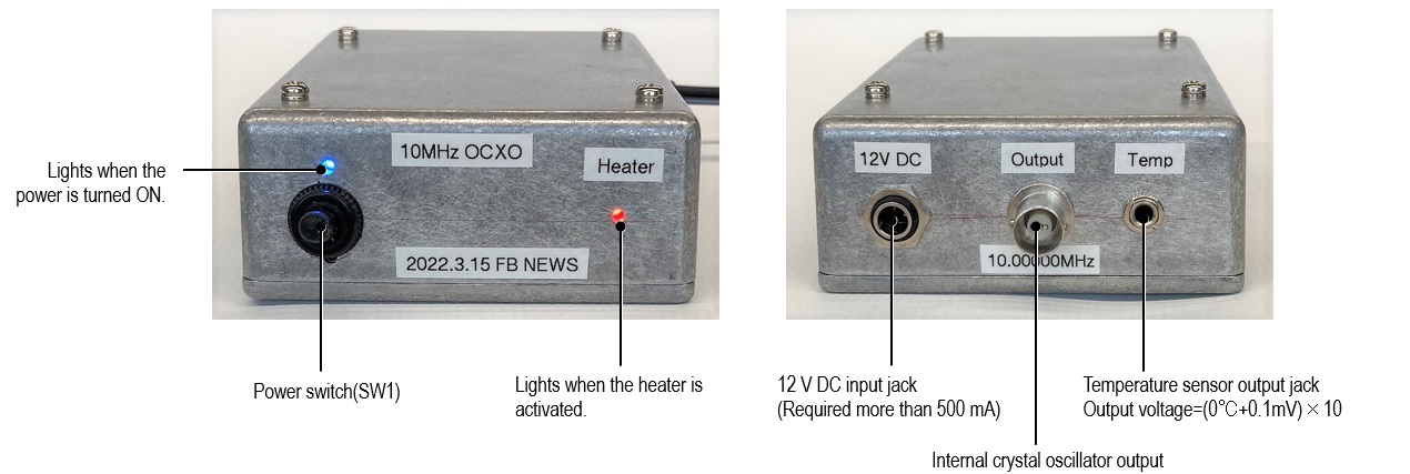
Figure 5. Front and rear panel layouts
Adjustment
Since the oscillation frequency of the crystal oscillator was 10.00000 MHz when the temperature of the crystal oscillator was 35 ┬░C in the experiment in the previous issue, the two adjustments shown below were made.
(1) Adjustment of the circuit that externally monitors the temperature inside the OCXO and calibration of the thermometer
(2) Adjustment and operation check of the control circuit to maintain a constant temperature inside the OCXO
(1) Adjustment of the circuit for externally monitoring the temperature inside the OCXO and calibration of the thermometer
An LM35DZ-N (hereafter LM35) sensor, is installed inside the OCXO to detect the temperature. The output voltage of this sensor is described as 0 mV + 10 mV/┬░C in the National Semiconductor data sheet, and is shown in Figure 6.
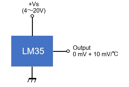
Figure 6. Typical application of the LM35
This means that the output voltage is 0 V at 0 ┬░C, and the output voltage rises by 10 mV for every 1 ┬░C rise in temperature. By monitoring this voltage externally, the temperature inside the OCXO can be determined. Generally, the oscillation frequency of a crystal oscillator is greatly affected by the external temperature, and this temperature is controlled so that a signal with a stable frequency can be extracted.
Figure 7 compares the output voltage of the LM35 with both calculated and measured values, showing that at a low temperature of 6.5 ┬░C, the error between the calculated and measured values is as much as 2 ┬░C, but at near room temperature the error is not so great and is less than 1 ┬░C. As mentioned in the previous issue, the oscillation frequency of the crystal oscillator used in this project is known to output 10.00000 MHz at 35 ┬░C. Although I do not have the measured output voltage data at 35 ┬░C, I will proceed with the design with the expectation that the error will not be so large.
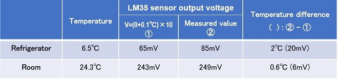
Figure 7. Output voltage on LM35 in different environments
The output terminal of the LM35 is connected to an amplification circuit with a voltage amplification factor of 10 times, configured with IC4. The output is passed through the IC3(b) buffer to display the internal temperature of the OCXO externally, as the temperature output with a voltage of 1/10 of the temperature. For example, if the temperature inside the OCXO is 30 ┬░C, a voltage of 3 V is output to the Temperature output pin. Conversely, the value displayed by the voltmeter multiplied by 10 will be the temperature inside the OCXO. To calibrate the temperature display, adjust R7 so that the value is 1/10 of the temperature at the time of measurement. (Calibration should be performed as close to 35 ┬░C as possible.)
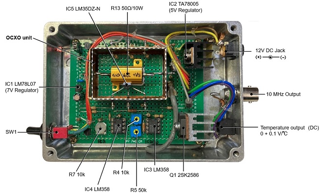
Figure 8. Inside the 10 MHz reference signal generator
(2) Adjust the control circuit to maintain a constant temperature inside the OCXO and check operation
Turn ON the power. When R4 or R5 is rotated, there is a point where the red LED indicating the operation of the heater, turns ON or OFF. When this LED turns on, it indicates that the heater inside the OCXO is turned ON and the heater is radiating heat.
Since preliminary experiments have shown that the oscillation frequency is exactly 10.00000 MHz at 35 ┬░C, the output voltage is calculated to be 0.35 V (=10 mV x 35). Adjust variable resistors R4 and R5 to set the voltage on pin 3 of IC3(a) to 3.5 V, which is 10 times the output voltage of the LM35. When the temperature of the LM35 is below 35 ┬░C inside the OCXO, the voltage on pin 2 of IC3(a) does not reach 3.5 V. The reference voltage on pin 3 of IC3(a) is higher, and pin 1 of IC3(a) goes High. When the LM35 is heated by the heater, and the voltage on pin 2 becomes 3.5 V or higher, pin 1 of IC3(a) goes low and the heater inside the OCXO turns OFF. This is repeated, as necessary.
Confirmation of the circuit operation
I placed the completed 10 MHz reference signal generator in a refrigerator for a while to allow the enclosure to cool sufficiently. After removing it, I quickly connected the power supply and voltmeter to the main unit (Figure 9). I connected a frequency counter to the output jack with the gate time set to 10 sec. With the crystal oscillator used in this experiment, the output frequency was more than 100 Hz higher than 10.00000 MHz when the enclosure was cool. This depends on the crystal oscillator used.
When the power is turned ON, the red LED lights to indicate that the heater is energized. At this time, you can check the temperature inside the OCXO by connecting a voltmeter to the temperature output. The red LED will be lit continuously for a while, but when the temperature inside the OCXO reaches 35 ┬░C, the LED will turn OFF. After about 5 minutes, the inside of the OCXO will be warmed up and the heater will turn ON and OFF every 2 to 3 minutes. 7 to 8 minutes later, the output frequency will gradually approach 10.00000 MHz and stabilize.

Figure 9. Connections
Operation test
The output waveform was still distorted, but I tested whether the 10 MHz signal output was stable. For the test, I used Icom's IC-9700, 144/430/1200 MHz All mode transceiver. The IC-9700 has an input connector to operate with a 10 MHz external reference signal. I input the 10 MHz signal into the IC-9700 to confirm that it operates properly and oscillates at a stable frequency. Please note that if you will be using the expensive IC-9700 for this experiment, please conduct experiments at your own risk.
The IC-9700 requires ŌĆō10 dBm as the level of a 10 MHz external reference signal when you want to operate it with an external 10 MHz reference signal. Apply the 10 MHz reference signal to the [REF IN 10MHz] connector of the IC-9700 through an attenuator. I am especially interested in how it works on either SSB or CW on the 1200 MHz band. I checked the frequency stability while listening to SSB or CW signals. I did not feel that the frequency shifted significantly with time by ear. Although I have not been able to confirm this with an accurate measuring instrument, I found that the OCXO worked reasonably well.
Overcoming challenges
As explained earlier, when the power supply and ground are connected to a crystal oscillator and its waveform is observed on an oscilloscope, the waveform is distorted, as shown by the yellow line in Figure 10. Since the crystal oscillator is originally used as a clock for logic circuits, a square wave suitable for logic circuits can be obtained by clipping this waveform with a diode and passing it through a waveform shaping circuit. In this case, the output waveform should be a sine wave since it is a 10 MHz reference signal.
A Low Pass filter (LPF) can be adjusted by observing the output waveform with an oscilloscope and turning the variable trimmer capacitor to get as close to a sine wave as possible.
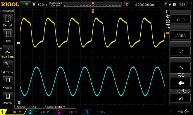
Figure 10. Signal waveform when output signal is passed through a LPF. (Blue line)
Effect of load on output waveform
The sine wave of the output waveform will collapse, depending on the load connected to the output terminals. The inductance and capacitance connected to the load affect the circuitry inside the crystal oscillator, and to obtain a clean sine wave, the LPF, connected to the output terminal must be designed accordingly.
Summary
A 10 MHz reference signal generator with an OCXO was built for the purpose of reducing frequency fluctuations due to temperature changes. The finished reference signal generator was left outdoors for about one hour. After it cooled down sufficiently, it was quickly taken into the shack and the passage of time and the display of the frequency counter at that time were recorded. Figure 11 shows the graph.
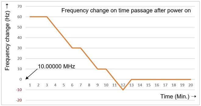
Figure 11. Frequency change on time passage after power ON
CL
Short BreakŃĆĆbacknumber
- How many colors do you see when a colored disc is rotated at high speed?
- Making a dual Positive/Negative voltage power supply in a single box, for experiments
- Building of an RF Volt-Ammeter for QRP operation
- White noise generator project
- One day electronics project ŌĆō Making a simple antenna tuner for QRP operations
- Can the RHM12 portable antenna be matched with a bicycle body on HF?
- Making an ŌĆ£ON AIRŌĆØ lamp using LM358
- Making a simple anemometer
- Making a sound machine say ŌĆ£Good morning. Thank you for everything.ŌĆØ
- Electronics project for the 10 MHz reference signal generator (2)
- Electronics project for the 10 MHz reference signal generator (1)
- Making a straight type AM radio using a TA7642 IC
- About splitters
- Electronics project for FB NEWS: Making a decoration light string
- Making a Simple Electric Field Strength Meter
- Building a simple QRP power meter
- Building a 20 Amp electronic DC load device using an N-channel MOSFET for the load
- Building an automatic backup power switching unit
- Overvoltage protection device using LM358: Part 2
- Building an Over Voltage Protector: Part 1
- Making a 50 MHz monoband MLA without a variable capacitor
- Making a 50 MHz monoband MLA.
- Let's connect a computer headset to the IC-705
- Building a microphone selector
- Building an audio amplifier using an LM386 IC chip
- An External Keypad for Icom Transceivers
- After all, is the receiver good for Up-conversion?
- Find the gain of the stack antenna
- The mystery of controlling the microphone and PTT with only two wires
- RFID tag