


Short Break
One day electronics project – Making a simple antenna tuner for QRP operations

Completed antenna tuner for QRP operations
This time, I will introduce a simple antenna tuner for QRP operations that can be made with readily available parts.
Required impedance matching
An antenna tuner is a matching circuit inserted between a radio and an antenna to efficiently transfer the RF (Radio Frequency) signal from the transmitter to the antenna, or from the antenna to the radio.
In particular, in order to efficiently transmit signals from an RF amplifier circuit to the next stage without attenuation, it is important that the output impedance of the amplifier circuit match the input impedance of the side receiving the signal. If matching is not achieved, the signal from the transmitter is not efficiently transferred to the input side of the next stage, such as an antenna, and as a result, reflected waves are generated. As the reflected waves travel back and forth in the circuit, signals that overlap with the original signal are input to the circuit in the next stage, resulting in waveform distortion and causing unwanted radiation.
Figure 1 (left) is a block diagram of an AF (Audio Frequency) amplifier. Efficient power transfer means that the output resistance of the first stage (R1) is equal to the input resistance of the second stage (R2) that receives it. Figure 1 (right) shows a transmitter and antenna. To efficiently transmit the output signal to the antenna, the condition Z1 = Z2 is required, as in the AF amplifier.
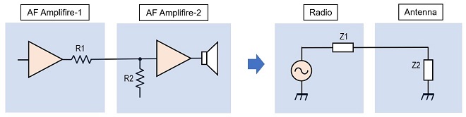
Figure 1. Left: The maximum power is generated at the speaker when R1=R2
Right: Similarly in the antenna circuit, the maximum power is radiated from the antenna when Z1 = Z2
In AF amplification circuits, the effect of reactance on the frequency of coils and capacitors does not need to be considered so much because the frequencies handled are low, but this is not the case at RF. Even a small amount of inductance or capacitance on the order of MHz will produce an impedance that cannot be ignored. Therefore, as shown in Figure 2, the antenna tuner works to make the impedance from the transmitter side (Z1) to the antenna side (Z4), as close to the same as possible.
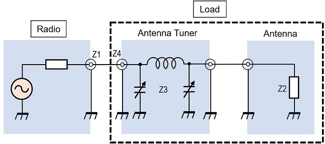
Figure 2. Matching circuit including antenna tuner
Target specifications for the antenna tuner
When we start making an antenna tuner, coils and variable capacitors are always necessary. Coils can be made by oneself, but variable capacitors are difficult to make by oneself, and it has recently become difficult to obtain them in the market. The antenna tuner for QRP with 5 W or less can be made using the well-known plastic variable capacitors for germanium radios, so I chose the antenna tuner for QRP with 5 W or less.
・Matching frequency range: 7 to 28 MHz
・Type of matching circuit: π (Pi) matching circuit
・Built-in matching status indicator (as you like)
・Maximum input power: 5 W PEP (Output power when using IC-705 battery pack)
・Single 260 pF Plastic variable capacitors are used for tuning
・Light weight and small size
・No power supply required
Schematic diagram
The schematic diagrams are shown in Figures 3 and 4 below. The antenna tuner part in Figures 3 and 4 are identical. If you want an antenna tuner for QRP without considering complicated circuits, you only need to make the "Antenna Tuner" part shown in the figures. The Power detection part shown in Figure 3 and the SWR detection part shown in Figure 4 are optional circuits.
The matching circuit is called π (Pi) type matching circuit, and the coil of L1 is wound on a toroidal core to make it a compact size. Since matching with the antenna cannot be performed over a wide frequency band by only adjusting the variable capacitor at both ends of L1, the inductance of the coil should also be varied. The inductance of the coil is tapped at an appropriate number of turns, and the inductance is switched with a 12-contact rotary switch.
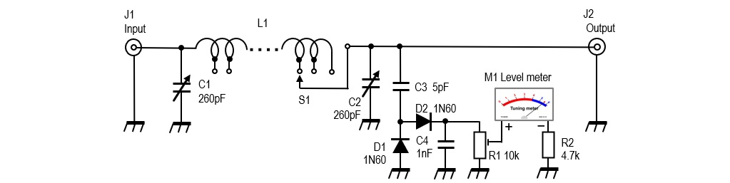
Figure 3. A π-type antenna tuner (with power detection circuit)

Figure 4. A π-type antenna tuner (with SWR detection circuit)
Building an antenna tuner
(1) Making a coil with a toroidal core
The key parts are the coil and variable capacitor. If you are not concerned about weight reduction or miniaturization, any variable capacitor will do, but you will want a variable capacitor with a capacity of at least 250 pF. This time, the coil is wound on a toroidal core to make it smaller, but an air-core coil is also acceptable if there is enough space.
The toroidal core used in this project was purchased at an amateur radio flea market. I have no idea of the part number or specifications. Based on my past experience, I thought if I wind the core 40 times, it will result in an inductance of about 30 µH. Later, I measured the inductance with a meter and found it to be 36 µH. There were other toroidal cores that I had purchased at other flea markets, so I chose one at random and made a coil in the same way, which resulted in a coil with a similar inductance.
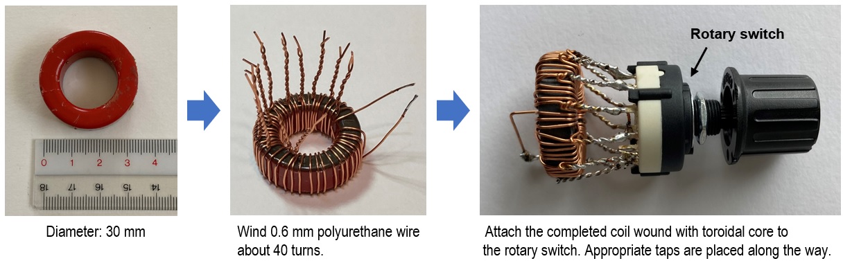
Figure 5. Making a coil with a toroidal core
For reference, Figure 6 shows the tap positions of coils wound on a toroidal core and their respective inductances measured with a measuring instrument.
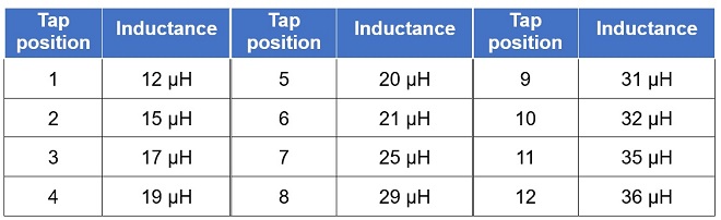
Figure 6. Number of turns and inductance of the coil shown in Figure 5 (actual measurements)
I do not know the specifications of the toroidal core used to detect SWR either. The toroidal core had an actual diameter of 10 mm and an inner diameter of 5 mm. This core is wound 10 times with 0.3 mm polyurethane wire. The winding on the toroidal core serves as a transformer rather than a coil. The primary side inputs the RF supplied from the transceiver to the antenna tuner, and the secondary side detects the signal and detects the traveling wave or reflected wave.
(2) Meter
As mentioned above, if you are making a simple antenna tuner, additional circuits for power detection and SWR detection are not necessary. The meter I used was also purchased at a flea market. The specifications were unknown, but when I measured it, I found that it was a small current indicator with a full scale of about 0.1 mA. In addition, the SWR may deteriorate due to the installation of a detection circuit.
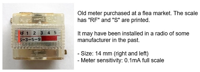
Figure 7. A meter used in the detection circuits
(3) Assembling
The antenna tuner was assembled in a plastic case because I wanted to make it lightweight. The weight of the completed antenna tuner was 160 g. Figure 8 shows an internal view of the one with the power detection circuit (left) and the one with the SWR detection circuit (right). The antenna tuner part is identical.

Figure 8. Antenna tuner built into a plastic case
Left: With power detection circuit Right: With SWR detection circuit
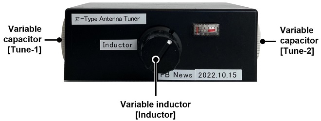
Figure 9. Completed antenna tuner
Adjusting the antenna tuner
There is nothing in particular to adjust in terms of the circuitry. After confirming the wiring, connect a 50 Ω dummy load through the antenna tuner made for IC-705 as shown in Figure 10.
Set the IC-705 to either FM or RTTY. For the IC-705 meter display, push the [MENU] button on the IC-705 front panel and select "METER" to display the SWR status in advance. Set the frequency to 14 MHz, near the center of the HF band, and the PO meter will swing when the IC-705 is set to transmit. Turn the [Inductor] knob on the front panel of the antenna tuner you have made to minimize the indication of the SWR meter. Once the SWR meter is minimized, turn Tune-2 (variable capacitor on the output side) and adjust it so that the meter indication is minimized. Turn Tune-1 (input side variable capacitor) further so that the meter indication becomes minimum. Since a 50 Ω dummy load is connected, the SWR meter of the IC-705 should not indicate at all. Similarly, check the operation in the frequency range of 7 MHz to 28 MHz.
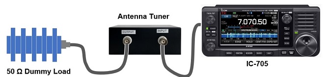
Figure 10. Checking the operation of the antenna tuner with a 50 Ω dummy load
The next step is to connect the actual antenna and check its operation. The method is the same as for the 50 Ω dummy load.
Adjustment of the Power detection circuit
In the circuit diagram shown in Figure 3, R1 is a 10 kΩ variable resistor. When the antenna tuner is adjusted to maximum power, adjust R1 to set the meter to full scale. If the sensitivity of your meter is less than 0.1mA, the meter may not reach full scale even if R1 is adjusted. In that case, increase the capacitance of C3 a little to increase the meter runout. However, this is the same as picking up of the output, so the transmit power sent to the antenna will be slightly reduced.
Adjustment of the SWR detection circuit
The adjustment points are C5, C8, and R5, shown in Figure 4. With a 50 Ω dummy load connected to the antenna tuner, first adjust the antenna with variable capacitors [Tune-1] and [Tune-2] so that SWR=1. Next, turn C5 and C8 to minimize the meter runout with the transmission as it is. If the SWR of the antenna connected to the antenna tuner deteriorates, the meter may swing out during transmission. In that case, adjust R5 to full scale.
Impressions
The specifications were set from 7 to 28 MHz for the matching frequency range, but the inductance of the coil wound on the toroidal core was higher than expected and it worked as an antenna tuner even at 3.5 MHz. However, the capacitance of the variable capacitor was insufficient and the SWR was just under 2 at the 3.5 MHz band. The HF high band such as 21 MHz and above were no problem at all. Measurements with NanoVNA showed that matching was possible up to 36 MHz, but not up to 50 MHz.
CL
Short Break backnumber
- How many colors do you see when a colored disc is rotated at high speed?
- Making a dual Positive/Negative voltage power supply in a single box, for experiments
- Building of an RF Volt-Ammeter for QRP operation
- White noise generator project
- One day electronics project – Making a simple antenna tuner for QRP operations
- Can the RHM12 portable antenna be matched with a bicycle body on HF?
- Making an “ON AIR” lamp using LM358
- Making a simple anemometer
- Making a sound machine say “Good morning. Thank you for everything.”
- Electronics project for the 10 MHz reference signal generator (2)
- Electronics project for the 10 MHz reference signal generator (1)
- Making a straight type AM radio using a TA7642 IC
- About splitters
- Electronics project for FB NEWS: Making a decoration light string
- Making a Simple Electric Field Strength Meter
- Building a simple QRP power meter
- Building a 20 Amp electronic DC load device using an N-channel MOSFET for the load
- Building an automatic backup power switching unit
- Overvoltage protection device using LM358: Part 2
- Building an Over Voltage Protector: Part 1
- Making a 50 MHz monoband MLA without a variable capacitor
- Making a 50 MHz monoband MLA.
- Let's connect a computer headset to the IC-705
- Building a microphone selector
- Building an audio amplifier using an LM386 IC chip
- An External Keypad for Icom Transceivers
- After all, is the receiver good for Up-conversion?
- Find the gain of the stack antenna
- The mystery of controlling the microphone and PTT with only two wires
- RFID tag