


Short Break
Making a simple anemometer
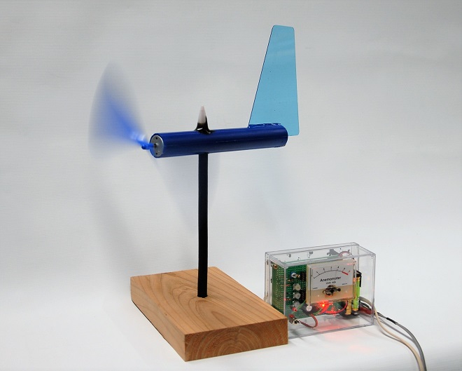
Completed prototype of a simple anemometer
When the wind blows, we, amateur radio operators, worry about whether or not our outdoor antennas will be blown away. To try to feel such wind with quantitative values, I made a simple anemometer using materials I had on hand as prototype. Although it cannot be used as a measuring instrument like commercially available anemometers because the indicated value does not correspond to the wind speed announced by a meteorological agency, it may be applicable to amateur radio and daily life by allowing us to feel the strength of the wind in numerical form.
Produce both wind speed and wind direction meters
At first, I planned to produce a meter for wind speed and wind direction. However, I found that it was difficult to produce a sensor to detect wind direction. I even planned to purchase a commercially available sensor, but I found that the hurdles were quite high in terms of processing the output signal and physically mounting the sensor, so I decided to abandon the wind direction function this time, leaving just the wind speed.
For reference, the sensor to detect wind speed is a 12 V DC motor with brushes, which is used for plastic models. To detect wind direction, a potentiometer, a so-called "rotation angle sensor," is required. The output needs to be converted from analog to digital, and the circuit is complicated, so this is a homework assignment for my future project.
Circuit diagram of the simple anemometer
Figure 1 shows the circuit diagram of the simple anemometer I made. Although the values of each component are fixed, the output voltage varies depending on the specifications of the motor used, so the values must be changed accordingly.
The key point of the meter is the sensor part that converts wind speed into an electrical signal. Normally, when voltage is applied to the terminals of a DC motor, the shaft of the motor rotates, and the rotation is converted into power. This time, however, I use the opposite phenomenon, so when the shaft is rotated, a voltage proportional to that rotation is output from the motor terminals.
The circuit composed of IC1A in Figure 1 is a circuit that turns ON a "warning light (red LED)" to indicate when the wind speed reaches a certain level.
The circuit uses an LM358N, operational amplifire (Op-Amp) commonly used in electronic projects. It is an 8-pin IC with two Op-Amps built into one package. IC1B amplifies the voltage generated by the motor, and the drive circuit is configured to move the meter in the latter stage. This allows the 1 mA ammeter to swing to full scale. In principle, it is possible to make the 1 mA ammeter swing just by the output voltage of the motor, but the impedance of the circuit connected to the motor is made high so as not to affect the operation of other circuits.
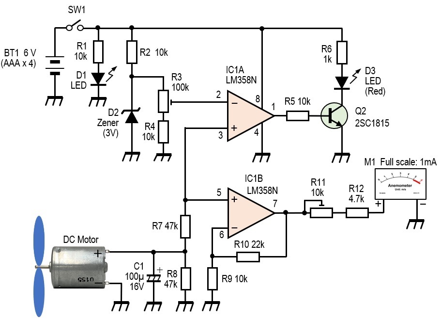
Figure 1. Circuit diagram of a simple anemometer
Since a power supply with an AC adapter was originally planned for this circuit, a Zener diode was used for D2 to stabilize the reference voltage applied to pin 2 of IC1A. However, if the power supply for the circuit is a pure DC power supply, like a battery with no voltage fluctuation as in this case, the constant voltage circuit consisting of R2 and D2 is unnecessary. The Zener diode is left in place in consideration of operating the circuit with an AC power supply in the future.
Constructing the anemometer
(1) Installation of the DC motor
A DC motor with brushes was used for the part that detects wind speed. Among several types of DC motors, I selected a DC motor with a high output voltage that rotates well, even in light winds. The wind propeller is the same as that used in rubber band-powered airplanes. When the shaft of the motor rotates, it induces a voltage at the terminals. This induced voltage is used to numerically display the wind speed.
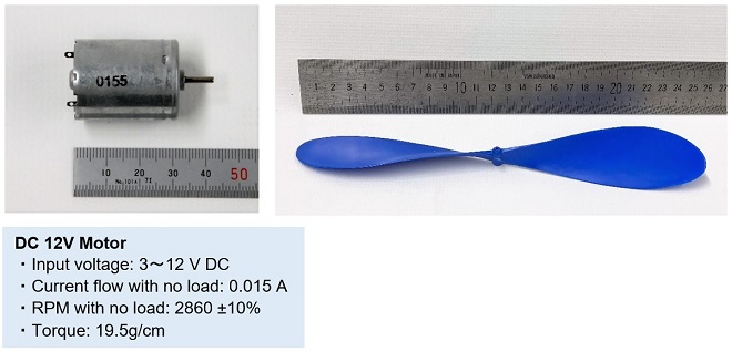
Figure 2. DC motor sensor that converts wind speed to voltage and the plastic propeller
(2) Extracting the output voltage from the motor
It is necessary to devise a way to prevent the lead wires connected to the motor terminals from twisting when the wind direction changes, and the anemometer boom rotates. I used a coaxial cable for this solution. The coaxial cable must be as thick as possible for structural reasons. The core and braided wires of the coaxial cable are energized by contacting the copper plate brushes attached to the motor output terminals. This structure is shown in (3) Internal Structure of Anemometer below.
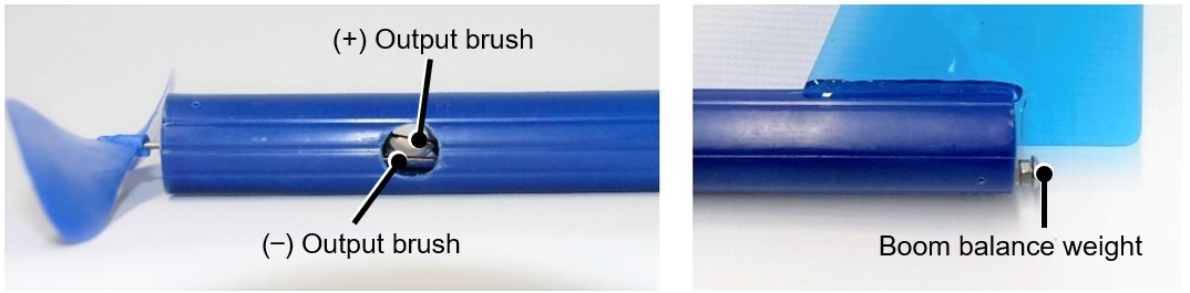
Figure 3. Brushes (left) connected to the motor output terminals and balancing screws (right)
(3) Internal structure of an anemometer
Since this unit was made as a prototype, the anemometer itself is not waterproof, and the way it would be mounted outdoors was taken into consideration. Also, the boom support is not strong enough to support the anemometer, as the coaxial cable is exposed. It is necessary to consider waterproof construction and robustness to withstand a certain degree of wind speed for actual outdoor installation.
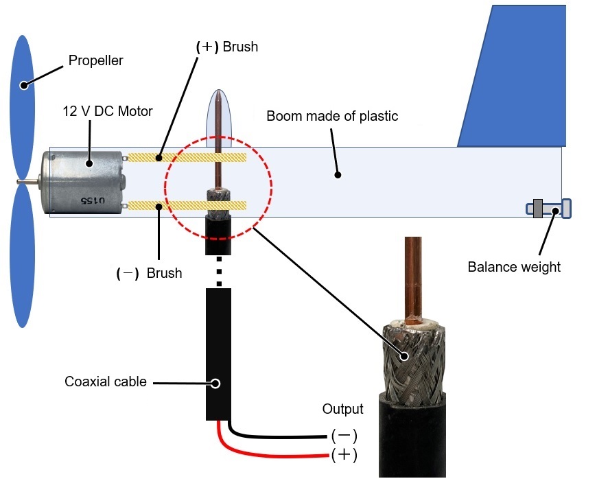
Figure 4. Internal structure of a simple anemometer
(4) Making the electronic circuit on a PCB
The circuit shown in Figure 1 was built on a 7 cm x 9 cm universal circuit board. The finished board was placed in a ready-made acrylic case to complete the prototype.
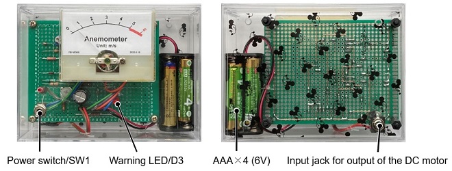
Figure 5. Display unit with embedded circuit board
Calibrating the anemometer
(1) Calibration with a fan
It is necessary to quantitatively know the strength of the wind for calibration. Therefore, I used a commercially available anemometer to determine the wind speed, and I calibrated the meter of the anemometer I made based on that wind speed. Since the wind blowing outdoors can be strong or weak, I calibrated the anemometer using the wind generated indoors by a household fan.
The fan is equipped with a switch that sets the wind strength to [High], [Medium], or [Low]. When the distance between the fan and the commercial anemometer was 1 meter, the wind speed was measured as shown in Figure 6 below.
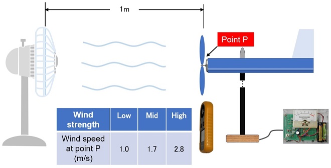
Figure 6. Calibrating the prototype anemometer with a fan and a commercial anemometer.
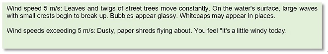
Even with the wind speed of the fan set to "High" and the commercial anemometer close to the fan screen, the wind speed did not exceed 4.5 m/s. Then, how much is a wind speed of 5 m/s or even higher than 4.5 m/s? The explanation on the Japan Meteorological Agency's website and related websites states the following:
Since a household fan could not produce winds of 4.5 m/s or higher, I set the scale of the anemometer I made to 6 m/s, which is slightly stronger than 4.5 m/s. Since there is a proportional relationship between the motor's rotation speed and its output voltage, Figure 7 shows a scale plate made by dividing a 1 mA ammeter into six equal parts.
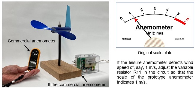
Figure 7. Calibration of anemometer and making of the scale plate
(2) Adjustment of wind speed warning LED
According to the explanation of wind speed by the Japan Meteorological Agency, we feel that "the wind is getting a little stronger" when the wind speed exceeds 5 m/s. Therefore, I made the red LED (D3) turn ON when the wind speed exceeds 5 m/s for the prototype anemometer. Since it is impossible to create an exact wind speed of 5 m/s, I will create a wind of 4.5 m/s, the maximum wind speed that can be created indoors, and adjust R3 in the circuit diagram to turn ON the warning LED at that time.
Summary
The making of the anemometer was supposed to be an opportunity to lower the crank-up antenna tower by sounding an alarm when strong winds begin to blow, but surprisingly, I struggled to create a simulated strong wind. If the anemometer is to be installed outdoors, waterproofing measures are necessary, and it is also necessary to ensure that the anemometer itself does not fly away when strong winds blow, so I felt the hurdles to construct it were high.
CL
<Reference materials>
From the Japan Meteorological Agency's explanation of "Wind Strength and Blowing Directions"
Short Break backnumber
- How many colors do you see when a colored disc is rotated at high speed?
- Making a dual Positive/Negative voltage power supply in a single box, for experiments
- Building of an RF Volt-Ammeter for QRP operation
- White noise generator project
- One day electronics project – Making a simple antenna tuner for QRP operations
- Can the RHM12 portable antenna be matched with a bicycle body on HF?
- Making an “ON AIR” lamp using LM358
- Making a simple anemometer
- Making a sound machine say “Good morning. Thank you for everything.”
- Electronics project for the 10 MHz reference signal generator (2)
- Electronics project for the 10 MHz reference signal generator (1)
- Making a straight type AM radio using a TA7642 IC
- About splitters
- Electronics project for FB NEWS: Making a decoration light string
- Making a Simple Electric Field Strength Meter
- Building a simple QRP power meter
- Building a 20 Amp electronic DC load device using an N-channel MOSFET for the load
- Building an automatic backup power switching unit
- Overvoltage protection device using LM358: Part 2
- Building an Over Voltage Protector: Part 1
- Making a 50 MHz monoband MLA without a variable capacitor
- Making a 50 MHz monoband MLA.
- Let's connect a computer headset to the IC-705
- Building a microphone selector
- Building an audio amplifier using an LM386 IC chip
- An External Keypad for Icom Transceivers
- After all, is the receiver good for Up-conversion?
- Find the gain of the stack antenna
- The mystery of controlling the microphone and PTT with only two wires
- RFID tag