


Short Break
Let's connect a computer headset to the IC-705
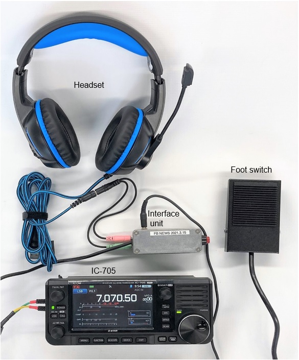
I feel that the remote-work has become widespread in Japan to prevent infection of the new coronavirus. This time, I will build an interface unit that enables the IC-705 to use a headset that is often used in video conferencing while working remotely.
I realized that it was surprisingly convenient to actually operate the completed interface unit and headset for personal computers with the IC-705, so I bought a headset from a major online shopping site.
Although it is convenient, PTT is inevitably pushed with a finger, so I thought "let's connect a foot switch and make it completely hands-free" in this article. Since the PTT switch is pushed with your foot, both hands are completely free. With both your arms in front of the radio, you can operate in a relaxed mood.
Connection diagram
No active components are used in building the unit. I think it is easy to build it because it is just soldering components and wiring. The most time consuming part of the construction was drilling holes in the aluminum diecast case.
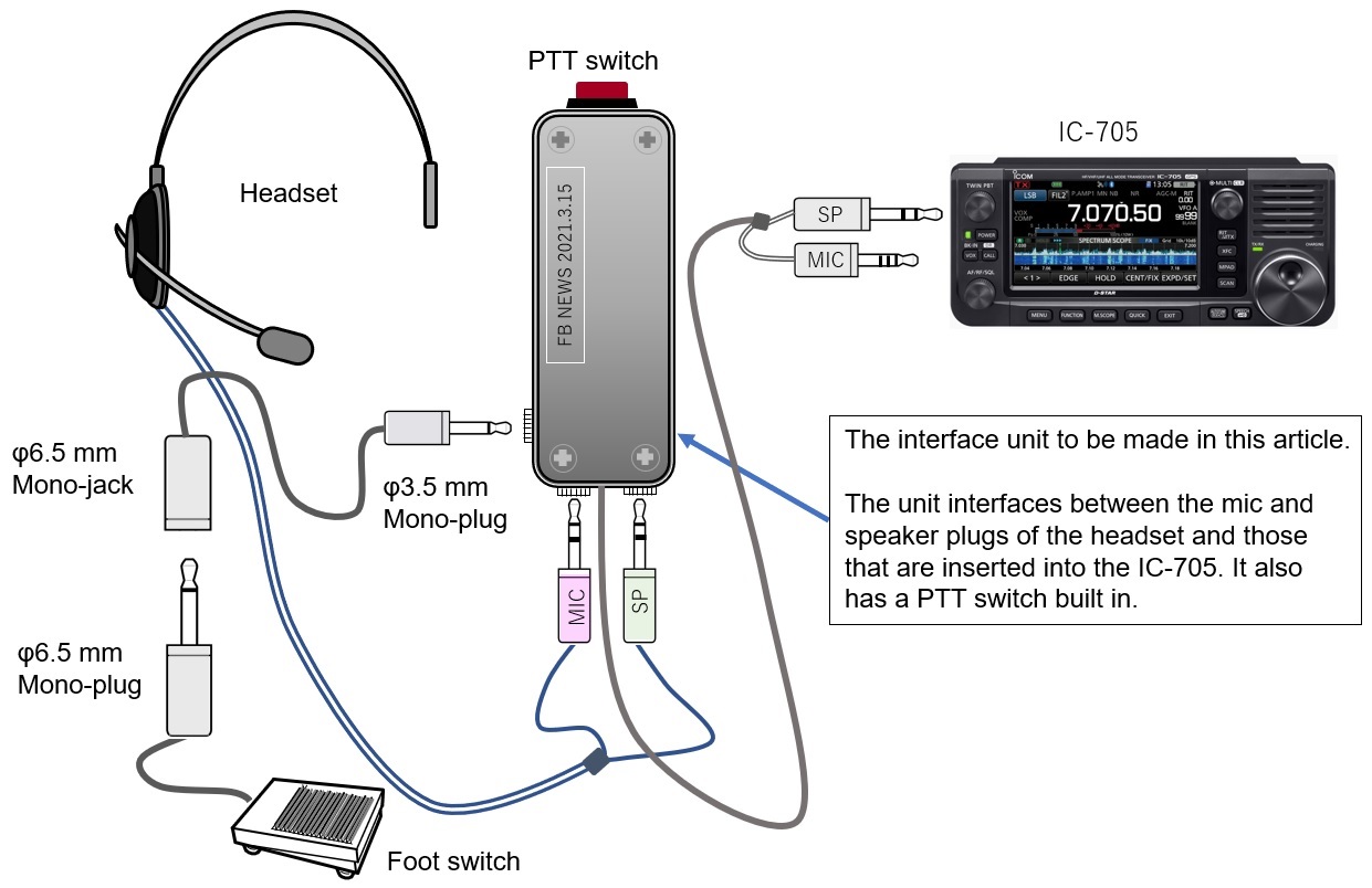
Figure 1. Connection diagram between the interface unit and external devices
Wiring diagram
A wiring diagram may be more appropriate than a circuit diagram. The wiring diagram shown in Figure 2 is based on the article "How to operate the IC-705 with a desktop microphone " introduced in the technical segment of the February 2021 issue of the FB NEWS Worldwide. The link to the article is: https://www.fbnews.jp/202102/ww05/
The unit even works without capacitors C2 and C3, but they are added to prevent RF feedback, just in case.
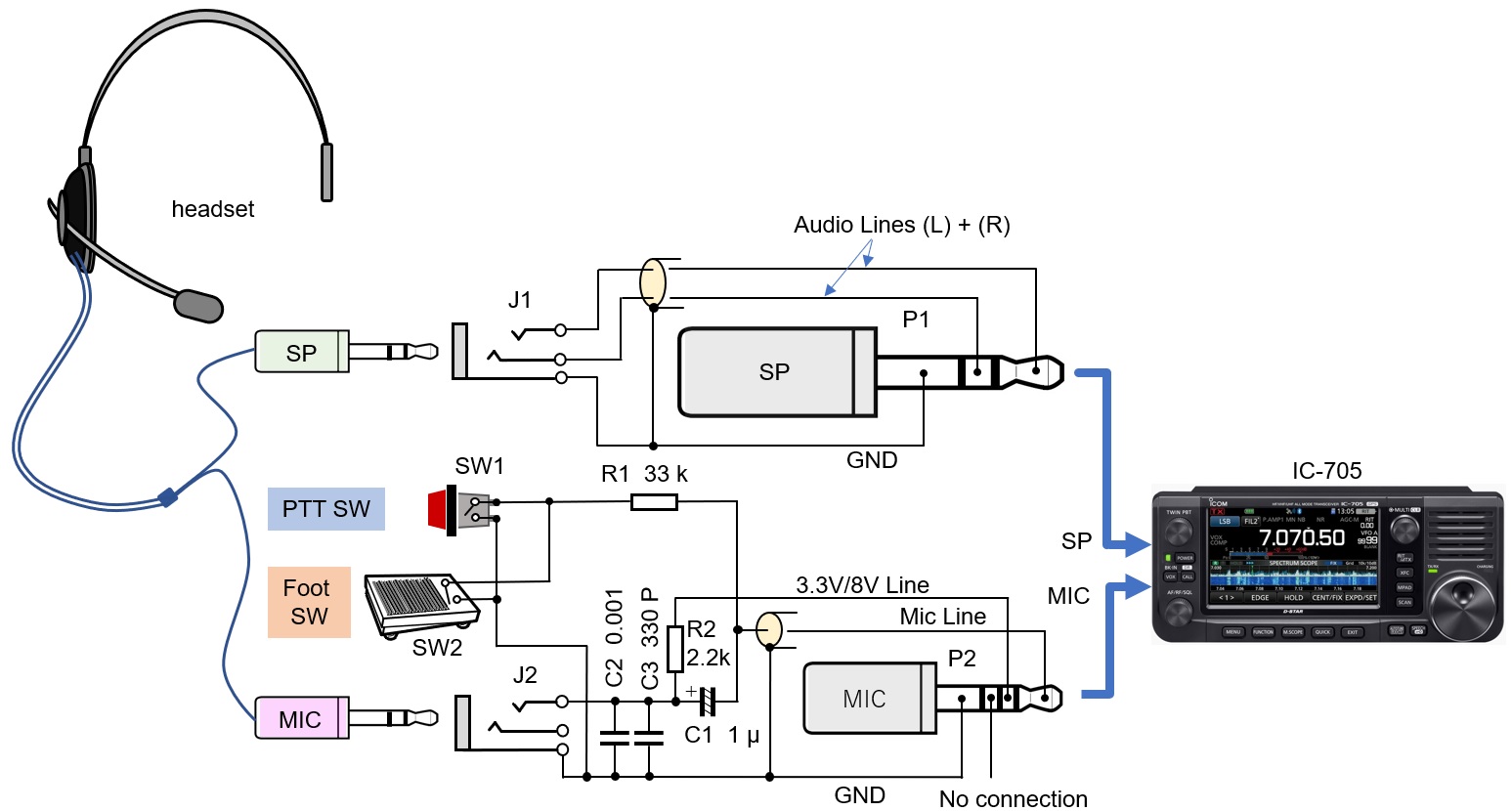
Figure 2. Wiring diagram
Shape of the interface unit
The headset I bought at an on-line shopping site does not have a PTT switch because it is used for TV conferencing, so I install one in the interface unit. The interface unit should be handheld, and the PTT switch should be thumb pressable. In addition, I devised a way to install a foot switch function to make activating PTT completely hands free.
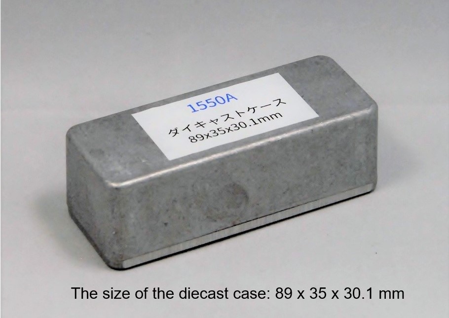
Figure 3. The shape and dimensions Figure 3. The shape and dimensions of the aluminum case
Headset specifications
There are three major types of headset plugs on the market, as shown in Figure 4. I decided to use a headset with separate φ3.5 mm SP and MIC plugs. I have confirmed that even a φ3.5 mm 4-pole plug can also be used without problems by using a conversion cable, as shown in Figure 5. I did not confirm whether a USB plug would work or not because I did not have a conversion cable.
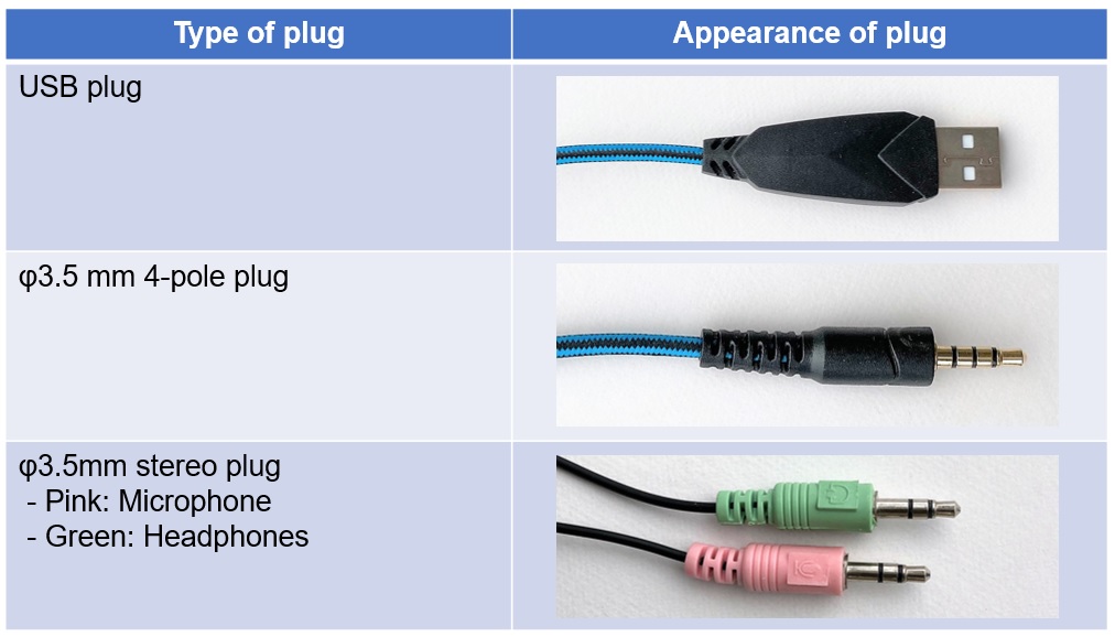
Figure 4. Shapes of the plugs used in headsets
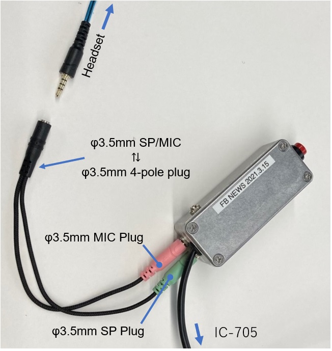
Figure 5. Connections with the conversion cable
Installing the PTT and foot switches
The headset used in this project does not have a PTT switch, as mentioned above, so I added one to the unit. It is not necessary to modify the IC-705 itself to add the PTT switch that is mounted on the case. I use a momentary switch that turns ON only while I push it. If you replace this PTT switch with a foot switch, you can switch between transmission and reception with your foot, so both hands are completely free.
(1) PTT switch
The PTT circuit of Icom's radios are unique. You simply connect the MIC line through a 33 kΩ resistor to GND to transmit and disconnect it to receive. This operating principle is published in the October 2020 issue, Short Break of the FB NEWS Worldwide. The link is:
https://www.fbnews.jp/202010/ww03/
(2) Foot switch
The foot switch is connected internally in parallel with the PTT switch. For the connection, I used one connector as shown in Figure 6 and wired it neatly.

Figure 6. Inside view
The foot switch shown in Figure 7 is sold in parts shops in Nipponbashi, Osaka. There are three cables coming out of the foot switch. This time, I connected a φ6.5 mm monaural plug to the cable end that is connected when the foot switch is pushed. Normally, it would be best if this φ6.5 mm plug could be directly connected to the interface unit built in the previous issue, but the φ6.5 mm jack is too large to be installed in this interface unit. I had no choice but to install a φ3.5 mm jack and made a conversion cable to connect between the φ6.5 mm and φ3.5 mm plugs.
The connection circuit is not particularly difficult. You can simply connect the foot switch in parallel with the PTT switch you installed earlier. The wiring diagram is shown below. The foot switch is labeled SW2 in the wiring diagram in Figure 2.
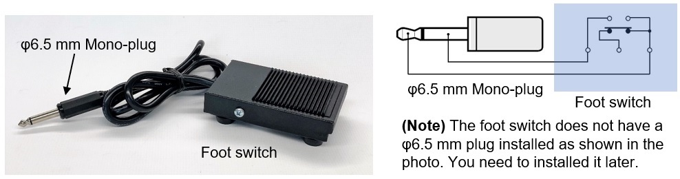
Figure 7. Foot switch
Parts list
Figure 8 is the parts list. I used header-pins and their housing connectors for the convenience of building, but they are not listed in the parts list because it does not matter which ones you use.
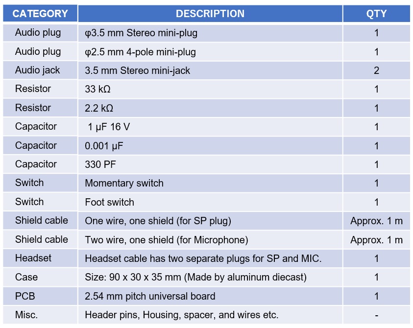
Figure 8. Parts list
Assembling
I chose a slender case so that I could hold it in my hand. In considering shielding from RF signals, I chose an aluminum die-cast case. The PTT switch was installed as the red switch shown in Figure 6 above, assuming that it is pushed with the thumb. I put a small board in the case. This is used for wiring the relay for the SP and MIC on the headset and on the IC-705. It would be a rat's nest of wire without the board. So, it is better to insert a board to connect more firmly, and I think that the inside layout is cleaner.
Audio output from the headphones
If your headset has two channels, left (L) and right (R), make the following settings in the IC-705 set mode to output audio from both headphones.
[MENU]> [SET]> [External Terminal]> [SP Terminal Function]> [Headphones (L + R)]
Check the setting of the voltage to the ECM
Most headset microphones used in video conferencing and computer games are Electret Condenser Microphone (ECM), so an external voltage is needed. The voltage is applied from the IC-705 through a 2.2 kΩ resistor.
Figure 9 shown below is the specifications of the IC-705 microphone jack, which is taken from the IC-705 instruction manual. Either 3.3 V or 8 V can be supplied from the microphone jack of the IC-705 for condenser microphones connected externally.
This voltage can be switched in the IC-705 set mode. It depends on the headset you are using, but in this project, set [MIC terminal 8V output] to [OFF]. You can check the settings by following the steps shown below.
[MENU]> [SET]> [External terminal]> [MIC terminal 8V output]> [OFF]
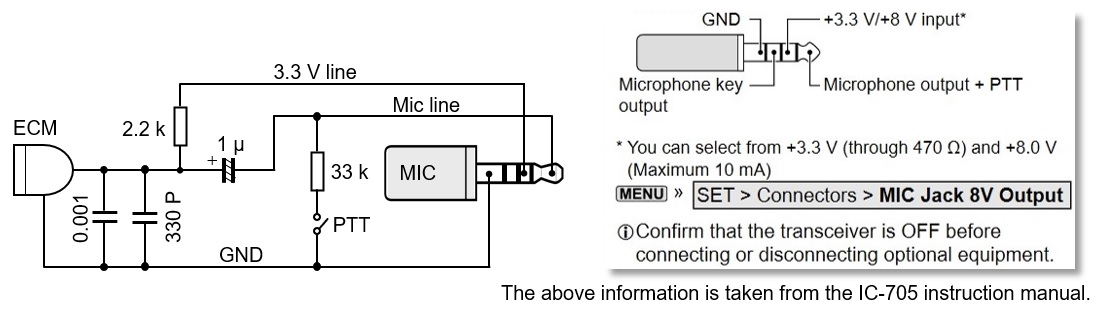
Figure 9. Microphone wiring diagram
CL
Short Break backnumber
- How many colors do you see when a colored disc is rotated at high speed?
- Making a dual Positive/Negative voltage power supply in a single box, for experiments
- Building of an RF Volt-Ammeter for QRP operation
- White noise generator project
- One day electronics project – Making a simple antenna tuner for QRP operations
- Can the RHM12 portable antenna be matched with a bicycle body on HF?
- Making an “ON AIR” lamp using LM358
- Making a simple anemometer
- Making a sound machine say “Good morning. Thank you for everything.”
- Electronics project for the 10 MHz reference signal generator (2)
- Electronics project for the 10 MHz reference signal generator (1)
- Making a straight type AM radio using a TA7642 IC
- About splitters
- Electronics project for FB NEWS: Making a decoration light string
- Making a Simple Electric Field Strength Meter
- Building a simple QRP power meter
- Building a 20 Amp electronic DC load device using an N-channel MOSFET for the load
- Building an automatic backup power switching unit
- Overvoltage protection device using LM358: Part 2
- Building an Over Voltage Protector: Part 1
- Making a 50 MHz monoband MLA without a variable capacitor
- Making a 50 MHz monoband MLA.
- Let's connect a computer headset to the IC-705
- Building a microphone selector
- Building an audio amplifier using an LM386 IC chip
- An External Keypad for Icom Transceivers
- After all, is the receiver good for Up-conversion?
- Find the gain of the stack antenna
- The mystery of controlling the microphone and PTT with only two wires
- RFID tag