


Short Break
Making an “ON AIR” lamp using LM358
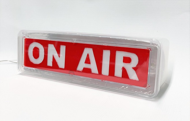
Completed ON AIR lamp
I will make an “ON AIR” lamp used in broadcast studios. The lamp will not be manually switched ON and OFF, but will detect radio signals you transmit and turn ON only when RF power is output.
Circuit diagram
The overall circuit diagram is shown in Figure 1. There are few components, and it can be made in a relatively short time because there is no need to make complicated adjustments.
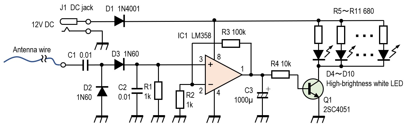
Figure 1. ON AIR lamp circuit diagram
Circuit description
The circuit consists of three parts; (1) a rectifier circuit that senses radio signals, (2) an amplifier circuit that amplifies the rectified signals, and (3) an LED drive circuit that turns ON high-brightness white LEDs instead of a light bulb.
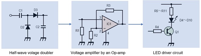
Figure 2. Block diagram of the ON AIR lamp
(1) Rectifier circuit
Radio signals picked up by the antenna are rectified to direct current in the half-wave voltage doubler. D2 and D3 are 1N60s, which is familiar in germanium radios. This is to minimize the voltage drop produced at both ends of the diodes.
The voltage drop at both ends of a silicon diode used for normal switching is about 0.7 V, but the 1N60 has a voltage drop as low as 0.2 V and rectifies even the weakest signals. A Schottky barrier diode with a low voltage drop, for example, can be used instead of a germanium diode.
(2) DC amplifier
The rectified DC signal is amplified by an LM358 general-purpose operational amplifier. It is a convenient Op-amp that operates on a single voltage power supply. The amplification factor is determined by the ratio of R2 and R3. In the experiment, a 1 MΩ variable resistor was used for R3 to adjust sensitivity. However, R3 is fixed with 100 kΩ resistor. If you think the gain is insufficient, you can change the resistance to higher than 100kΩ.
(3) LED drive circuit
A 1000 μF electrolytic capacitor is inserted at the output of LM358, between it and GND. This is to prevent the output of IC1 from going back to "L" as soon as the signal stops, which is not a problem until the circuit picks up a radio signal. The purpose is to hold the LED light ON.
A collector current of about 1 A should be selected for the Q1 transistor because several LEDs are driven at the same time. The standard for the high-brightness white LEDs used in this project states that the current should be 20 mA. 7 LEDs are connected in parallel, so the maximum current is 140 mA (20 mA x 7 LEDs = 140 mA). Since there were no suitable transistors on hand, I used a 2SC4051, although it has more than enough collector current.
Construction
Before starting construction, I designed the “ON AIR” lettering, preparing materials according to that image. Materials other than electronic parts were purchased at a DIY store.
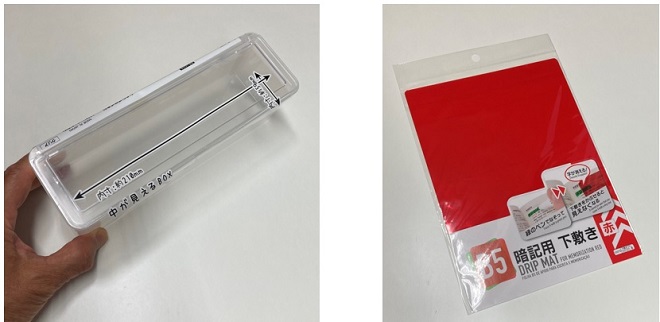
Figure 3. Case and acrylic plate procured at a DIY store
I cut out the words "ON AIR" with a sharp knife, as shown in Figure 4. When cutting out, be careful not to cut your fingers with the knife. This process took quite a bit of time, and it was difficult to get a good finish. I used an acrylic board because I had already purchased one, but after completion, I thought that red drawing paper would also be fine and finish beautifully, instead of an acrylic board which is difficult to process.

Figure 4. Cutting out an acrylic board patiently with a sharp knife
Next, I made the reflector that will be illuminated by LEDs from the back of the ON AIR letter. Aluminum foil is attached to the surface of a piece of cardboard for the reflector. The reflector should be concave, not flat, so that the LEDs emit a stronger light.
I made holes in the cardboard for the number of LEDs and insert them from the rear. Fix the LEDs to the cardboard with adhesive after insertion. Also, solder resistors R5 to R11 (680 Ω) as shown in the circuit diagram.
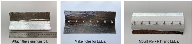
Figure 5. Making of the LED reflector
Components are mounted on a universal board. The cardboard on which the LEDs are mounted is concave, which eliminates height space in the case and allows the components on the board to lie on their sides.
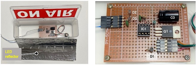
Figure 6. Integrating electronic circuits into the case
Figure 7 shows the LED reflector shown in Figure 5 integrated into the case.
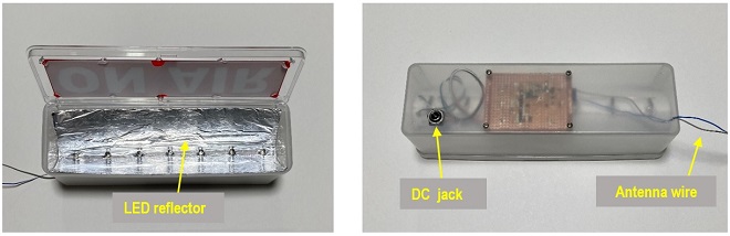
Figure 7. LED reflector and circuit board assembled inside the case
Summary
The appropriate length of wire used as the antenna is about 1 meter. The wire is wrapped several times around the coaxial cable through which the signal is transmitted. I have tried various lengths of wire in my shack. A length of about 2 meters makes it easier to pick up HF low band signals, but the lamp does not light up at the 144 MHz band. The lamp goes out when you stop speaking into the microphone, even if the transceiver is transmitting, because there is no signal at all times in the SSB mode.
This circuit is an application of the commonly known “Carrier control circuit.” This circuit is useful when you want to pick up radio signals and run some electronic circuit.
CL
Short Break backnumber
- How many colors do you see when a colored disc is rotated at high speed?
- Making a dual Positive/Negative voltage power supply in a single box, for experiments
- Building of an RF Volt-Ammeter for QRP operation
- White noise generator project
- One day electronics project – Making a simple antenna tuner for QRP operations
- Can the RHM12 portable antenna be matched with a bicycle body on HF?
- Making an “ON AIR” lamp using LM358
- Making a simple anemometer
- Making a sound machine say “Good morning. Thank you for everything.”
- Electronics project for the 10 MHz reference signal generator (2)
- Electronics project for the 10 MHz reference signal generator (1)
- Making a straight type AM radio using a TA7642 IC
- About splitters
- Electronics project for FB NEWS: Making a decoration light string
- Making a Simple Electric Field Strength Meter
- Building a simple QRP power meter
- Building a 20 Amp electronic DC load device using an N-channel MOSFET for the load
- Building an automatic backup power switching unit
- Overvoltage protection device using LM358: Part 2
- Building an Over Voltage Protector: Part 1
- Making a 50 MHz monoband MLA without a variable capacitor
- Making a 50 MHz monoband MLA.
- Let's connect a computer headset to the IC-705
- Building a microphone selector
- Building an audio amplifier using an LM386 IC chip
- An External Keypad for Icom Transceivers
- After all, is the receiver good for Up-conversion?
- Find the gain of the stack antenna
- The mystery of controlling the microphone and PTT with only two wires
- RFID tag