


Short Break
Making a dual Positive/Negative voltage power supply in a single box, for experiments
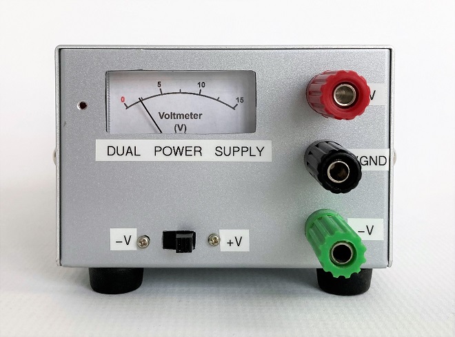
Completed positive and negative power supply
An article titled "Considerations when making a dual voltage power supply for operational amplifiers" was published in the March 2023 issue of the Monthly FB News. Although a dual voltage power supply has the advantage that it can be easily built with a small number of components by combining 78 series and 79 series three-terminal regulators, the output voltage cannot be changed. So, in this article, I will show you how I made an adjustable dual voltage power supply using the transistors and operational amplifiers listed in that article.
Specifications
(1) Output voltage
If you use your usual power supply with a variable voltage for the DC Input shown on the left side of the schematic diagram shown in Figure 1, the output of this power supply can be changed. The voltages appearing at +V and -V are half of the voltage applied to DC Input.
(2) Output current capacity
The current capacity depends on specifications of transistors Q1 and Q2. Q1 and Q2 used in this project were small-signal transistors due to the availability of components on hand, the maximum output current capacity is approximately 150 mA.
(3) Voltmeter
A voltmeter is installed to constantly check the output voltage. A schematic diagram of a voltmeter using a needle meter is shown at the right end of the circuit diagram. However, this is an extra circuit and should be added according to the intended use.
Schematic diagram
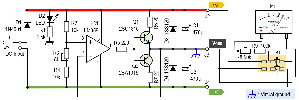
Figure 1 shows the circuit diagram made for this project. There are no components that are particularly difficult to obtain.
Components descriptions
(1) IC1 (LM358)
While most operational amplifiers operate with both positive and negative power supplies but this LM358 operates only with a positive single voltage. 2 operational amplifiers are built into the 8-pin IC package, but only one is used in this case. I use this operational amplifier as a comparator by comparing the voltage on the (+) and (-) terminals.
If the voltage on pin 3 is higher than the voltage on pin 2, the output on pin 1 is at the level of the positive power supply (Vcc). When the voltage on pin 3 is lower than that on pin 2, the output on pin 1 becomes 0 V. IC1 repeats this continuously to keep the output voltage constant.
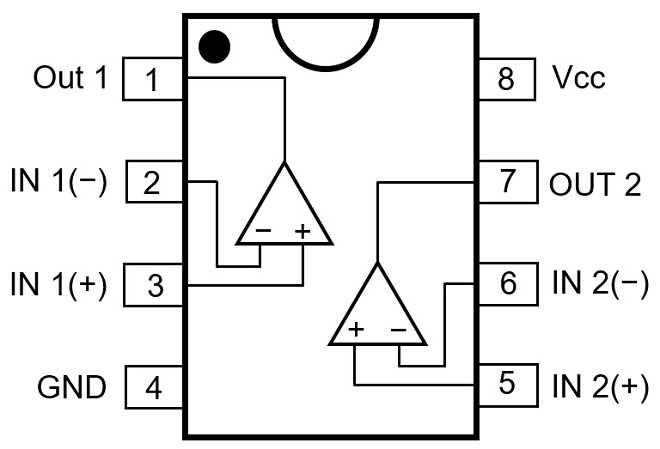
Figure 2. LM358 pin assignment
(2) Q1 and Q2
Q1 (2SC1815 NPN) and Q2 (2SA1015 PNP) are general-purpose transistors for small signals. These transistors differ between NPN and PNP, but the specifications are almost identical. Usually, this combination of NPN and PNP transistors with the same specification is called a complementary transistor and forms a push-pull circuit.
In this case, this combination of transistors was the only complementary transistor on hand. The current capacity may be a little low, but since this is an experimental power supply for operational amplifiers and does not require much current capacity, I used this combination.
(3) R3 (5 kΩ variable resistor)
A voltage of 1/2 of the input voltage is added to pin 3 of IC1. To create this voltage, a resistor of the same value is connected to the power supply, and the voltage at its midpoint is added to pin 3 (+) as the reference voltage. The 1/2 voltage created here appears as a positive and negative power supply output. The Q1 and Q2 used this time are almost the same complementary transistors, but this variable resistor is added to adjust the voltage that appears at the outputs of positive and negative outputs. If two resistors of the same value are connected, this variable resistor is not absolutely necessary, so omitting it is not a major problem.
(4) M1 (Voltmeter)
The meter is installed because I want to constantly check the output voltage. The meter is a simple plastic one attached to a receiver or FM tuner. The meter I used is a full scale 50 mA ammeter. I do not know the internal resistance, but I installed a voltage multiplier consisting of R8 and R9 and experimented and found that to make the meter a 5 V voltmeter, I should install a resistor of about 100 kΩ. Since the full scale needs to be adjusted in relation to the input voltage, R8 is a variable resistor of 50 kΩ, and R9 is a fixed resistor of 100 kΩ connected in series to make a multiplier.
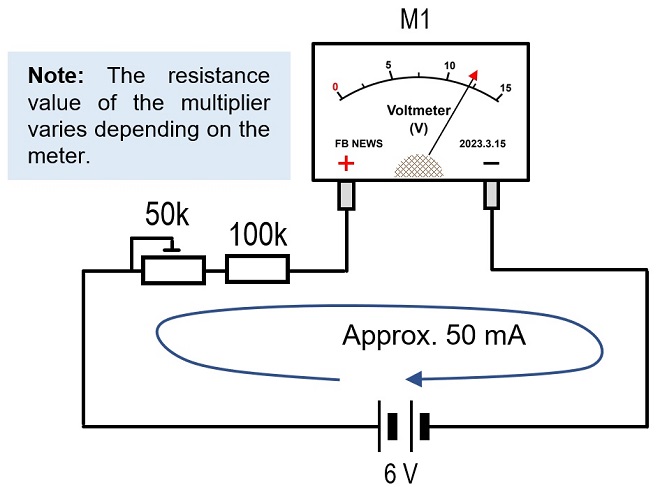
Figure 3. Full-scale 50 mA ammeter is converted to a voltmeter by attaching a voltage multiplier.
The meter scale is created in Word shown in Figure 4 below, printed out at a reduced size on a printer, and pasted onto the panel. The meter is adjusted with R8 (50 kΩ) shown in the circuit diagram.
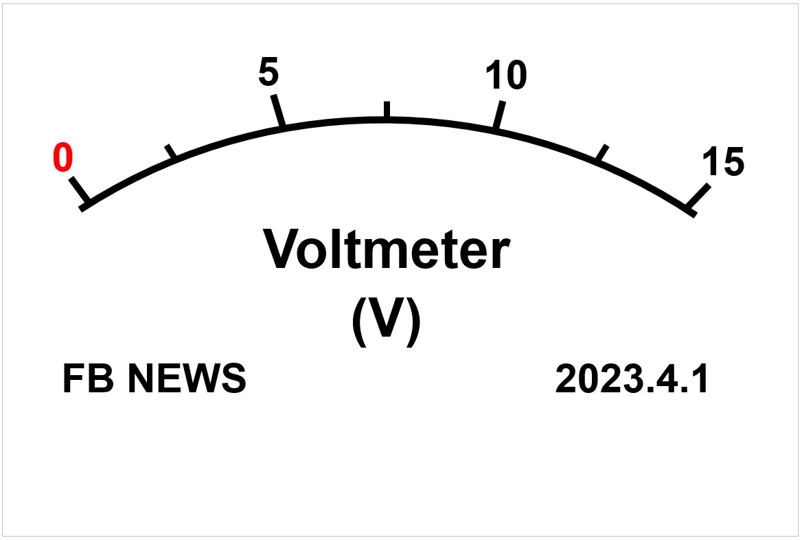
Figure 4. Sample of the meter scale
(5) S1 (slide switch)
Since positive and negative voltages should be checked at all times, the output voltage is switched by a two-circuit, two-contact (6P) slide switch. The M1 voltmeter described earlier is not particularly necessary and can be omitted if necessary.
(6) J2, J3, J4 (output pins)
Note that the ground (VGND) of the output terminals is different from the ground (GND) of the input power supply. The DC input ground must be separated from the output ground of both positive and negative outputs.
The VGND is usually called “Virtual ground.” The ground for electronic devices that have been made with a single power supply has been, for example, a metal chassis as a common ground for input and output. The terminal used for that output terminal must be isolated from the chassis, as shown in Figure 5(b), if it is to be built into a metal chassis.
If this power circuit is to be built into a case made of an insulating material such as plastic, either (a) or (b) can be used.
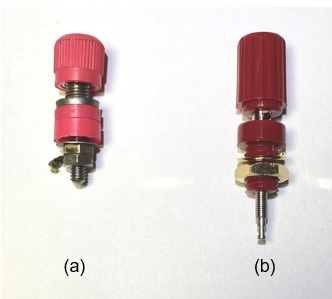
Figure 5. Two types of terminals with different usage
Assembling
An aluminum case measuring 125 mm x 90 mm x 60 mm was used. Since one of the specifications is to check the output voltage with a needle meter, the chassis has a hole for mounting the meter, as shown in Figure 6.
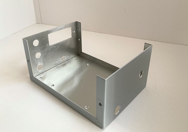
Figure 6. Aluminum chassis before component installation
When mounting the output terminals, it is convenient to set the distance between them to 18 mm so that the banana tip plug and BNC-J conversion connectors shown in Figure 7(b) can be mounted.
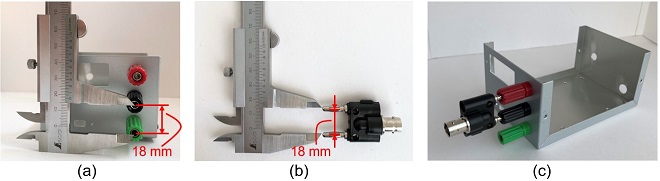
Figure 7. Make mounting holes for terminals to allow for the attachment of banana plugs.
Outside and internal views
Figure 8 shows each major part. This power supply is not equipped with a power switch to turn the power ON and OFF. The power supply is turned ON when the DC power supply is connected to the rear panel.
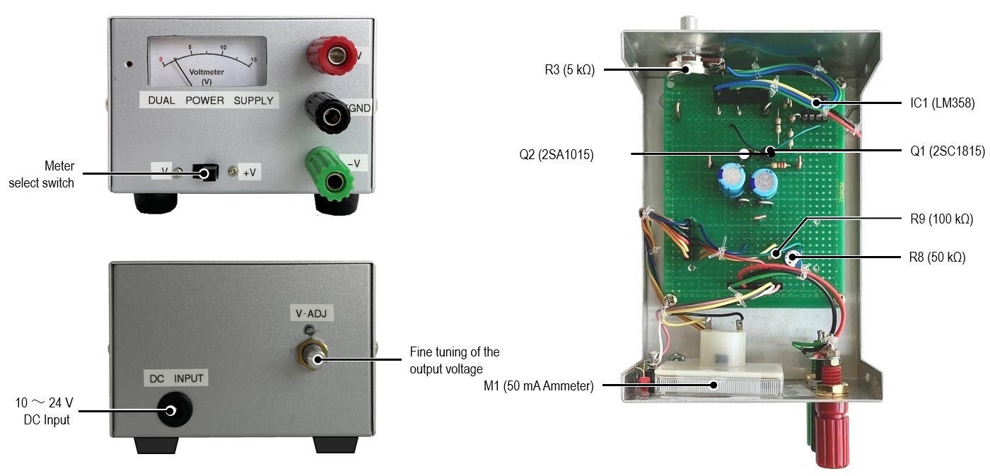
Figure 8. Outside and internal views
CL
Short Break backnumber
- How many colors do you see when a colored disc is rotated at high speed?
- Making a dual Positive/Negative voltage power supply in a single box, for experiments
- Building of an RF Volt-Ammeter for QRP operation
- White noise generator project
- One day electronics project – Making a simple antenna tuner for QRP operations
- Can the RHM12 portable antenna be matched with a bicycle body on HF?
- Making an “ON AIR” lamp using LM358
- Making a simple anemometer
- Making a sound machine say “Good morning. Thank you for everything.”
- Electronics project for the 10 MHz reference signal generator (2)
- Electronics project for the 10 MHz reference signal generator (1)
- Making a straight type AM radio using a TA7642 IC
- About splitters
- Electronics project for FB NEWS: Making a decoration light string
- Making a Simple Electric Field Strength Meter
- Building a simple QRP power meter
- Building a 20 Amp electronic DC load device using an N-channel MOSFET for the load
- Building an automatic backup power switching unit
- Overvoltage protection device using LM358: Part 2
- Building an Over Voltage Protector: Part 1
- Making a 50 MHz monoband MLA without a variable capacitor
- Making a 50 MHz monoband MLA.
- Let's connect a computer headset to the IC-705
- Building a microphone selector
- Building an audio amplifier using an LM386 IC chip
- An External Keypad for Icom Transceivers
- After all, is the receiver good for Up-conversion?
- Find the gain of the stack antenna
- The mystery of controlling the microphone and PTT with only two wires
- RFID tag