


Short Break
Building a microphone selector
Microphone selector
There are more microphones in my shack than there are radios. I have only one mouth and can only one transmit on one radio at a time, so one microphone is sufficient. However, when I find an unusual microphone, or a classic microphone at a flea market, I buy it on impulse.
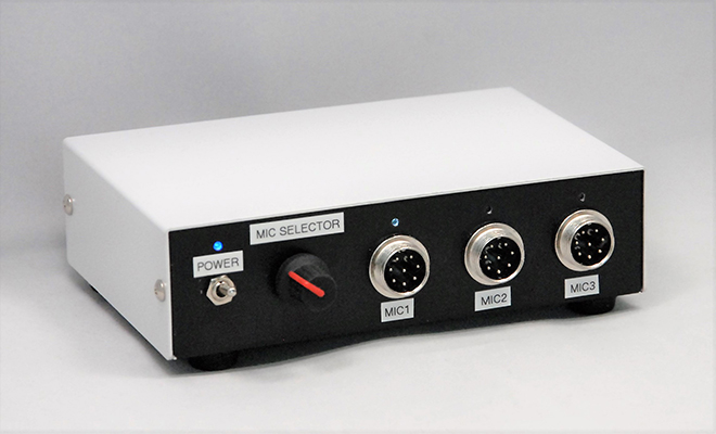
Figure 1. Completed microphone selector
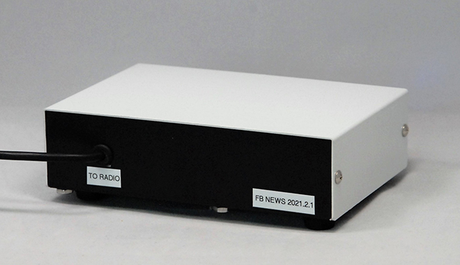
Figure 2. Rear panel of the completed microphone selector
Microphones can be enjoyable to look at for me, but the sound quality is still important. Whenever I make a QSO using a microphone I got at a flea market, I often ask the other station to give a report of the sound quality by saying "By the way, what about the sound quality of the microphone?" When the station says, "It has a punchy, heavy and calm sound." I am satisfied with my purchase.
The sound depends on the taste of the listener. I would like to compare sounds of the standard microphone that comes with the radio and a microphone that I got at a flea market. I built a "Microphone selector" unit that is convenient for amateur operators. There is no need for the troublesome work of disconnecting the microphone connector and replacing it with another microphone, asking "How about this microphone?" Switching is possible by simply turning the rotary switch position to 1, 2, or 3.
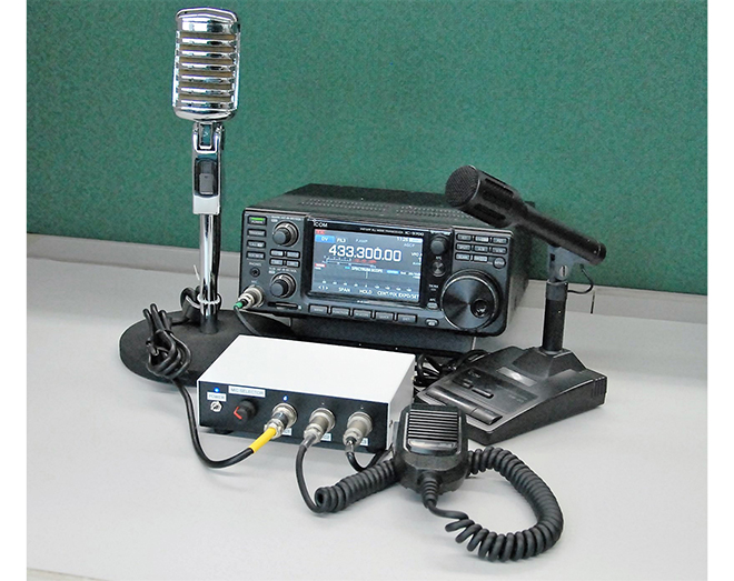
Figure 3. The microphone selector with three types of microphones connected.
I used a rotary switch to switch the microphone, but it does not switch the microphone signal itself. As you can see from the schematic diagram that will be posted later, the microphone input is switched by 2-bit H and L signals. There was also a desire to try using an IC for this audio selector once.
About the NJM2750 IC chip
This IC is originally designed for use as a stereo audio signal selector. The chip has a 4-input 1-output function. Since it has 4 inputs, 4 types of microphones can be connected to this selector and switched with a rotary switch. The IC supports stereo signals, but since it is used for radios, it uses only one channel.
This NJM2750 is a type of package called DMP16. It cannot be directly incorporated into a universal board with 2.54 mm pitch, which is often used in circuit building. Therefore, I assembled the DMP16 type chip and a universal conversion board that I purchased online.
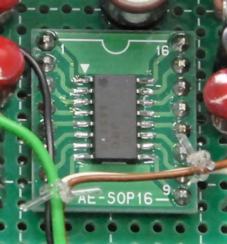
Figure 4. NJM2750 mounted on a 2.54 mm pitch conversion board
Schematic diagram
The IC used this time is from a Japanese manufacturer, New Japan Radio Company. The datasheet will be a quick hit on a net search. The schematic diagram is based on what was listed as an application circuit in the datasheet. This IC has 4 inputs and 1 output, but since there was not enough space on the aluminum case that I used, I could use only 3 input microphone jacks. If there is enough space on the case to be used, all 4 circuits can be used.

Figure 5. Microphone selector schematic diagram
Building the unit
The unit is operated by 6V, supplied by 4 AAA batteries. According to the datasheet, the operating voltage of the chip used is 4.7 to 13V, which is a sufficient range, so 6V is fine. I did not use an AC power supply this time because I was worried that noise from the power supply circuit and power supply hum noise would get into the microphone line if it were an AC power supply, so I chose a pure DC power supply dry cell battery construction.
Looking at the IC datasheet, there is no complicated circuits. The four 2-bit control signals are generated by SW1 and SW2. The 2-bit signal switches the input between 4 inputs inside the IC. As mentioned earlier, in this unit, 3 inputs are switched due to the mounting space of the microphone jacks.
The input can be switched by inputting a 2-bit control signal to pin 2 and pin 4 of the IC chip. The logic signal is shown in the table Figure 6. Since the control circuit does not need to be assembled with logic components, high and low are made by connecting H to 6V and L to the GND level as shown in the schematic diagram.
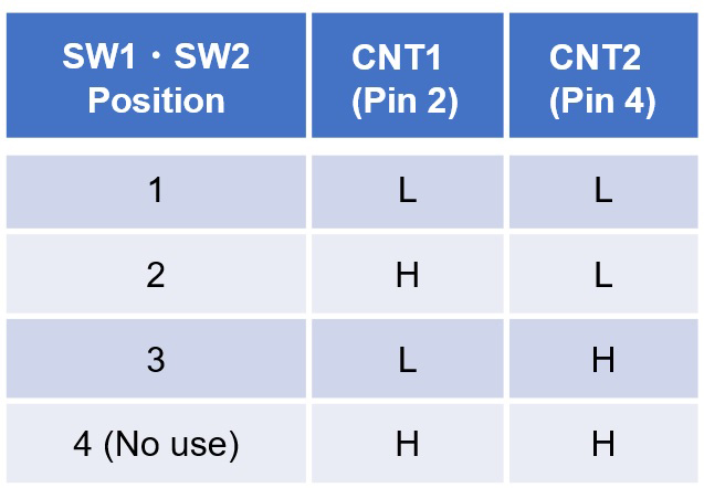
Figure 6. Switching circuit control logic
The 6 V is applied to the microphone line through the R4, R5 and R6 10kΩ resistors. This is because a condenser microphone requires a DC voltage applied. If you connect a dynamic microphone you do not need to apply a DC voltage to the microphone element. If you want to use both a condenser microphone and a dynamic microphone, you can install an ON/OFF switch to support either type of microphone.
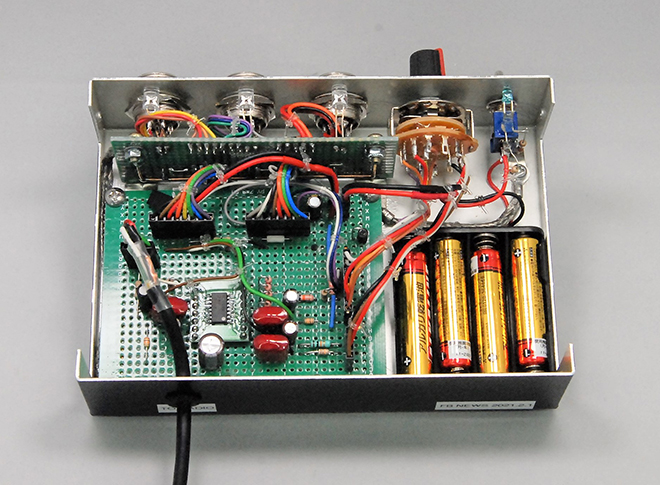
Figure 7. Inside of the microphone selector (Slightly different from the schematic diagram)
Completed
I put the PCB with all components are installed in an aluminum case so that it looks good, even in a shack. Although not shown in the schematic diagram, I added 3 LEDs on each microphone jack on the front panel so that I can see which microphone is connected.
CL
<Reference data>
NJM2750 datasheet in the New Japan Radio Company
Short Break backnumber
- How many colors do you see when a colored disc is rotated at high speed?
- Making a dual Positive/Negative voltage power supply in a single box, for experiments
- Building of an RF Volt-Ammeter for QRP operation
- White noise generator project
- One day electronics project – Making a simple antenna tuner for QRP operations
- Can the RHM12 portable antenna be matched with a bicycle body on HF?
- Making an “ON AIR” lamp using LM358
- Making a simple anemometer
- Making a sound machine say “Good morning. Thank you for everything.”
- Electronics project for the 10 MHz reference signal generator (2)
- Electronics project for the 10 MHz reference signal generator (1)
- Making a straight type AM radio using a TA7642 IC
- About splitters
- Electronics project for FB NEWS: Making a decoration light string
- Making a Simple Electric Field Strength Meter
- Building a simple QRP power meter
- Building a 20 Amp electronic DC load device using an N-channel MOSFET for the load
- Building an automatic backup power switching unit
- Overvoltage protection device using LM358: Part 2
- Building an Over Voltage Protector: Part 1
- Making a 50 MHz monoband MLA without a variable capacitor
- Making a 50 MHz monoband MLA.
- Let's connect a computer headset to the IC-705
- Building a microphone selector
- Building an audio amplifier using an LM386 IC chip
- An External Keypad for Icom Transceivers
- After all, is the receiver good for Up-conversion?
- Find the gain of the stack antenna
- The mystery of controlling the microphone and PTT with only two wires
- RFID tag