


Short Break
Electronics project for the 10 MHz reference signal generator
Part 1: Consideration of OCXO (Oven Controlled Crystal Oscillator)
OCXO unit
I have bought several crystal oscillators shown in Figure 1 at a flea market. These oscillators contain a crystal unit and its oscillation circuit in a metal case (can), and output a 10 MHz signal when a voltage of 5 V is applied.
“10.00000 MHz” is printed on the surface of the metal case, and the smallest digit is 10 Hz. We know that the oscillation frequency of a crystal unit varies with the ambient temperature. Since the one I purchased this time is not a crystal unit but a crystal oscillator, it is supposed to have a temperature compensation circuit built inside. I will look at the oscillation frequency with respect to temperature change, and will add temperature compensation to it, considering the stability and accuracy. This article will be divided into two parts, for (1) Consideration of the crystal oscillator characteristics and (2) Making an OCXO unit.
Performance of a 10.00000 MHz crystal oscillator
(1) Observation of the output waveform
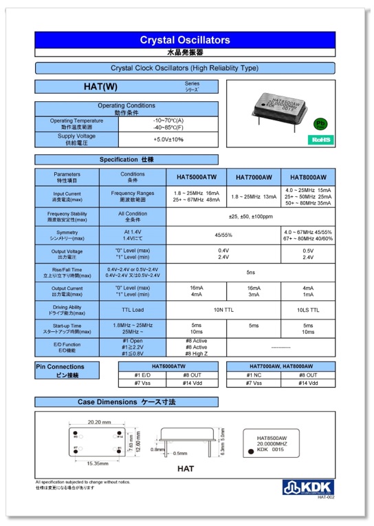
I did an online search for the data sheet of the HAT7500A crystal oscillator. The data sheet describes it as a "Crystal Oscillator", but it is also described as a "Crystal Clock Oscillator." I do not know if it can be used as a reference signal oscillator, but the data sheet says that the frequency stability, which is important for oscillators, is ±25 ppm under all conditions. As 1 ppm of 10.00000 MHz is 10 Hz. Therefore, ±25 ppm is 25 times higher than that, or 250 Hz. It depends on the application, but 250 Hz is a bit too large a deviation for a 10 MHz reference signal oscillator.
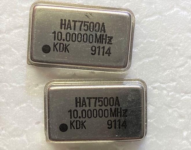
Figure 1. Two 10.00000 MHz crystal oscillators (size: 20 mm x 15 mm x 5 mm)
Figure 2 shows the output waveform of this crystal oscillator when a +5 V voltage is applied to it and observed with an oscilloscope. It is not a clean sine wave but distorted as a reference oscillator, but I will proceed with this study.
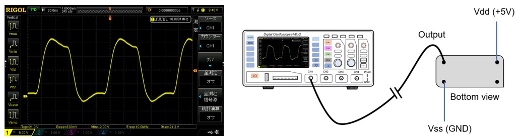
Figure 2. Wave form of the crystal oscillator
(2) Accuracy of the output frequency
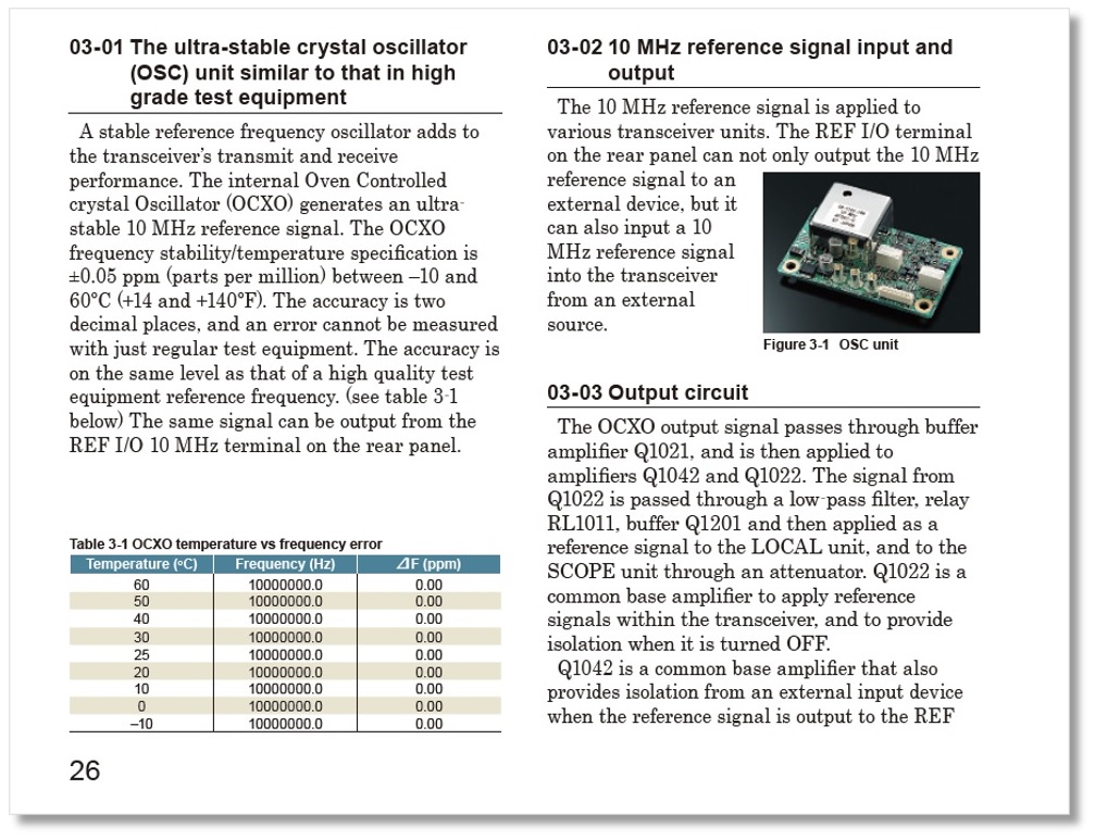
A frequency counter is used to measure the oscillator frequency. The accuracy of the frequency counter I have is not good enough, so I first turn ON the frequency counter for about one hour to stabilize the frequency of the reference signal built in the frequency counter. The accuracy of the reference signal of the Icom IC-7851 HF transceiver is ±0.05 ppm, which is an amazingly stable level. We will assume that the frequency of the reference signal of the IC-7851 does not change when the ambient temperature changes, and we have found a manual that describes the accuracy of the reference signal of the IC-7851, which is shown in Figure 3 for reference.
The display of the frequency counter in Figure 4 shows the result of the calibration. The frequency counter shows 10.00004 MHz (=10000040 Hz) even though the frequency of the reference signal of the IC-7851 is 1000000.0 Hz, indicating that the reference signal in the frequency counter has deviated. (Note: The smallest digit of the frequency counter does not show “0” and is treated as an unreliable digit.)
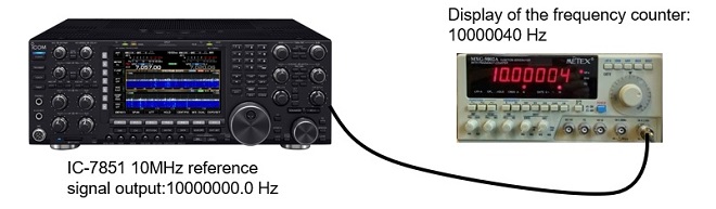
Figure 4. Calibration of the frequency counter (Gate time: 10 seconds)
In this state, I disconnected the IC-7851 and connected the output of the crystal oscillator to be measured by the frequency counter. Figure 5 shows the output frequency of the crystal oscillator. If it displays 10000040 Hz, the frequency is exactly 10 MHz, but the result displays 10000080 Hz, which is about 40 Hz higher. I replaced the oscillator with another crystal oscillator that I purchased, but the output frequency had a similar trend.
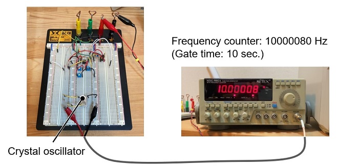
Figure 5. Output frequency of the crystal oscillator (room temperature: 23 °C)
(3) Temperature characteristics
Figure 6 shows the results of observing the trend of oscillation frequency versus temperature. The trend shows that the frequency of the crystal oscillator is high when the temperature is low and decreases when the temperature rises. Since the frequency counter displayed "10000040 Hz" when the temperature was 35 ℃, I can imagine that the oscillation frequency at this time is 10000000 Hz, which is exactly right.
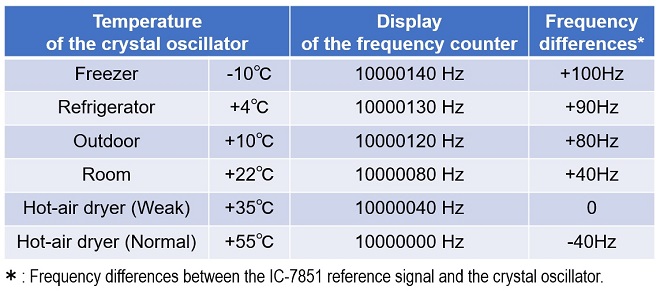
Figure 6. Temperature characteristics of crystal oscillator
Making an OCXO unit
OCXO is an abbreviation for Oven Controlled Xtal (Crystal) Oscillator. It is a crystal oscillator that electrically controls the temperature applied to the crystal unit to maintain a constant oscillation frequency. The oscillation frequency of the crystal oscillator to be used in this project is the same as that of the 10 MHz reference signal of the IC-7851 at +35 °C, as I showed above. Therefore, if the temperature of the crystal oscillator can be kept at +35 °C, the frequency of 10 MHz should always be obtained. However, if the outside temperature is below +35°C, it is possible to raise the temperature of the crystal oscillator to +35 °C by using a heater installed in the OCXO unit. If the frequency of the crystal oscillator can be varied, for example, to 10000000 Hz at +50 °C, it can always be heated by the built-in heater to keep it at +50 °C because the outside temperature never goes above +50 °C in Japan.
The OCXO uses a resistor as the heating element. When the temperature reaches a certain level, the current is stopped and turned OFF. When the temperature drops, the current is turned ON again to heat the resistor.
(1) Key parts of an OCXO
I will try to make an OCXO using the parts shown in Figure 7 and will use an LM35 temperature sensor (Figure 7 left) for the temperature sensing. The shape is specified as TO-92, the same type as a small transistor such as a 2SC1815. When the temperature is 0 °C, the output voltage of this LM35 is 0 V. The output voltage varies at a rate of 10 mV/°C. Therefore, if a voltmeter is connected to the output terminal and the voltmeter shows 10 mV, for example, the temperature is 1 °C. Figure 7 (center) is the resistor used to increase the temperature, which will serve as a heater. For the heater, we use a clad resistor for ease of use. Figure 7 (right) shows the 10.00000 MHz crystal oscillator to be used in this project.
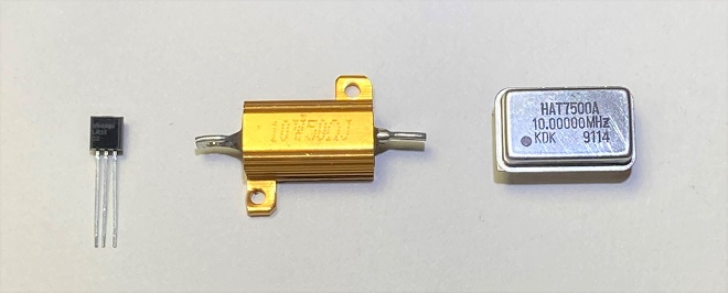
Figure 7. Key parts used for OCXO
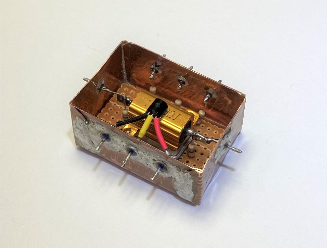
These components are stacked as shown in Figure 8 (left) and placed in a case made of copper plate. The connection between the components inside the case and the circuit outside is made through feed-through capacitors attached to the case, and the signal extraction through the feed-through capacitor for 10 MHz signals needs to be examined.
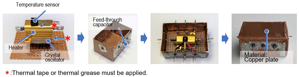
Figure 8. Construction process of the OCXO unit
(2) Temperature control configuration
Since the oscillation frequency of a crystal unit is easily affected by temperature, a circuit is made to maintain the temperature of the crystal unit at a constant level. Figure 9 shows the configuration of the control method. A current is applied to the heater to heat the crystal oscillator. In order to keep the temperature constant, the temperature of the heater is monitored by a temperature sensor. When the temperature reaches a predetermined level, the switch is automatically turned OFF to prevent the heater from getting any hotter, and the temperature rise of the heater is stopped. On the other hand, if the temperature drops, the heater will turn ON and heat up until it reaches the predetermined temperature.
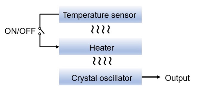
Figure 9. Temperature control configuration
(3) Examination of the circuit
Figure 10 shows a tentative experimental circuit in which a current is passed through R10 (cladding resistor) as a heater to heat the crystal oscillator of X1 to a predetermined temperature. IC4 (LM35) is a temperature sensor, which generates a voltage of 0 V at 0 °C and 10 mV for every 1 °C rise. The voltage generated by IC4 is amplified 10 times by IC3 to observe the temperature inside the OCXO unit externally. IC2(b) is a buffer that is added to prevent the control circuit from being affected by load fluctuations when an external voltmeter is connected.
IC2 is an operational amplifier, but it is used as a comparator in IC2(a) to compare the reference signal (voltage) made by the three-terminal regulator (IC1) with the voltage detected by LM35 (IC4). When the temperature in the crystal oscillator decreases, the voltage detected by IC4 decreases. The voltage is input to pin 2 of IC2(a) through IC3. IC2(a) compares the voltage on pin 2 with the voltage on pin 3 preset by R1, R2, and R3. If the voltage on pin 3 is higher, pin 1 outputs an H level and the MOSFET in Q1 is turned ON. As the temperature in the crystal oscillator rises, the voltage detected by IC4 also rises, and as a result, the voltage on pin 2 of IC2(a) becomes higher than the voltage on pin 3, and pin 1 of IC2(a) goes an L level. At this time, Q1 is turned OFF, and the heat generation in the OCXO stops. By repeating this process continuously, the temperature inside the OCXO is kept constant, and as a result, the output frequency of the crystal oscillator is stabilized.
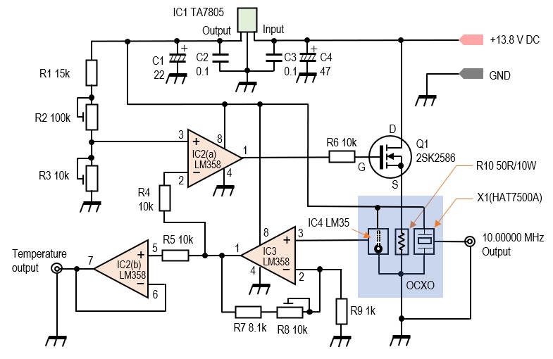
Figure 10. Experimental circuit incorporating OCXO
This is the end of the circuit consideration. This circuit has been verified on a breadboard, but since it is not the final circuit, I will verify this circuit further in the next article. In the next article, I would like to find out whether the signal is stable enough to withstand actual operation or not.
The attachment of the HAT7500A data sheet below was made possible with the cooperation and permission of Kyushu Dentsu Co., Ltd. (KDK) for publication. We would like to take this opportunity to thank them for their cooperation.
CL
Short Break backnumber
- How many colors do you see when a colored disc is rotated at high speed?
- Making a dual Positive/Negative voltage power supply in a single box, for experiments
- Building of an RF Volt-Ammeter for QRP operation
- White noise generator project
- One day electronics project – Making a simple antenna tuner for QRP operations
- Can the RHM12 portable antenna be matched with a bicycle body on HF?
- Making an “ON AIR” lamp using LM358
- Making a simple anemometer
- Making a sound machine say “Good morning. Thank you for everything.”
- Electronics project for the 10 MHz reference signal generator (2)
- Electronics project for the 10 MHz reference signal generator (1)
- Making a straight type AM radio using a TA7642 IC
- About splitters
- Electronics project for FB NEWS: Making a decoration light string
- Making a Simple Electric Field Strength Meter
- Building a simple QRP power meter
- Building a 20 Amp electronic DC load device using an N-channel MOSFET for the load
- Building an automatic backup power switching unit
- Overvoltage protection device using LM358: Part 2
- Building an Over Voltage Protector: Part 1
- Making a 50 MHz monoband MLA without a variable capacitor
- Making a 50 MHz monoband MLA.
- Let's connect a computer headset to the IC-705
- Building a microphone selector
- Building an audio amplifier using an LM386 IC chip
- An External Keypad for Icom Transceivers
- After all, is the receiver good for Up-conversion?
- Find the gain of the stack antenna
- The mystery of controlling the microphone and PTT with only two wires
- RFID tag